Hello,
i'm working on a tube preamp, it began with the restoration of a dynacord eminent amp, i removed the power section, inputs have been rewired to stereo, and it sound very good !
Now i have one unused 9 pin socket (used to be the phase inverter for the EL34s), and 2 signals coming from the plates of one 12AX7 (left and right channel).
That 2 signals sounds very good with just a 0,01uF cap from each plate, a 470k resistor and a 250k pot to ground, and then the pots feeding a sound card.
But i'd like to add 2 transformers to protect the sound card from potential DC (coupling cap failure) and give some more color to the sound.
With only 1 socket left, i can use one triode for each channel...
Any idea of the tube i could use and the arrangement ? i need some current to drive the transformer so maybe a 12AU7 ou a ECC88? single ended output, or cathode follower AC coupled ?
I will feed a sound card so i need line level.
Thanks !
I would suggest altering things so you don't have a 250K pot at the output. That is a horrible idea if you have more than a few inches of cabling between the output and your sound card.
With one socket left, consider adding a self biased cathode follower to drive your cables and the input impedance of your sound card.
I would not suggest adding a transformer just to assuage your paranoia regarding coupling cap failure. Transformers fail too! Have you ever experience either failing?
I agree with audiowize. Select a 600+ WVDC O/P coupling cap. of good quality, possibly a Multi-Cap PPFX part, and have done with the matter.
An ECC99 section per channel, as the cathode followers, will provide all the "grunt" needed to drive the cabling and load.
Definitely put the volume controls in the cathode followers' grid circuitry.
An ECC99 section per channel, as the cathode followers, will provide all the "grunt" needed to drive the cabling and load.
Definitely put the volume controls in the cathode followers' grid circuitry.
thanks,
i'll give it a try. but i tried to wire a cathode follower and sound was not as gound as before the CF...
i'll give it a try. but i tried to wire a cathode follower and sound was not as gound as before the CF...
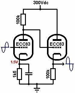
here it is... i had 2 triodes so i used both. it was before the stereo wiring.
output 1 sounds great
output 2 does not sound good...

output 1 sounds great
output 2 does not sound good...
I can't really discern what you've drawn all that well, but it's not correct.
You need a self biasing cathode follower. You can look it up on the internet to get some ideas about how to design it.
How much B+ do you have?
You need a self biasing cathode follower. You can look it up on the internet to get some ideas about how to design it.
How much B+ do you have?
that's what i wired :
B+ at thate node is 380V DC
The Valve Wizard
ok, as i'm a guitar amp guy, it seems i chose the wrong arrangement, that creates distorsion 😀
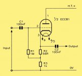
is it what i need :

but my B+ is way higher !
B+ at thate node is 380V DC
The Valve Wizard
ok, as i'm a guitar amp guy, it seems i chose the wrong arrangement, that creates distorsion 😀
is it what i need :
but my B+ is way higher !
Last edited:
OK, so you're adding 15-20dB of gain by doing that, do you need another 15-20dB of gain? The ECC83 is about the worst double triode to use for a cathode follower, as you can't run much current through it.
Try just adding a self biasing cathode follower. Use a 6CG7, 6922, or 12AU7. Run 3-5mA through the cathode follower.
Try just adding a self biasing cathode follower. Use a 6CG7, 6922, or 12AU7. Run 3-5mA through the cathode follower.
That's a tricky DC coupled setup.
A sample self biased cathode follower schematic is provided. Look carefully and you'll see things that are part of a mundane self biased common cathode gain block. For instance, R2 is a cathode bias resistor.
BTW, because of low gm, the triodes in a 12AX7/ECC83 make POOR cathode followers.
Attachments
Last edited:
Eli's Mullard yellow drawing is a good one, but I wouldn't necessarily use those resistor values. I would use a 12AU7 and change:
R3 to 30K/3W (Vishay PR-03 is good here)
R2 to 1K 1/8W
R1 stays the same
C1 stays the same
C2 becomes 2.2uF/250V
R3 to 30K/3W (Vishay PR-03 is good here)
R2 to 1K 1/8W
R1 stays the same
C1 stays the same
C2 becomes 2.2uF/250V
Thanks
i did not begin from scratch, hence the use of a ECC83 and the first gain stage that was in the original circuit
but i'm gonna rebuilt it and try with a ECC81 or ECC82 - wich one's the best for that use ?
i did not begin from scratch, hence the use of a ECC83 and the first gain stage that was in the original circuit
but i'm gonna rebuilt it and try with a ECC81 or ECC82 - wich one's the best for that use ?
The ECC82 is a little better suited to this use, especially because its heater cathode voltage ratings are higher, and your cathode follower should be sitting right at about 150V.
High gm "rules" in cathode followers, as that equates to a desirable low O/P impedance. That says go 12AT7/ECC81. However, plate current is also a factor, as charging and discharging cable capacitance matters. The ECC99 I previously suggested exhibits both high gm and high plate current. 🙂  The ECC99 exhibits favorable characteristics in both of the important parameters.
The ECC99 exhibits favorable characteristics in both of the important parameters.The ECC82 is a little better suited to this use, especially because its heater cathode voltage ratings are higher, and your cathode follower should be sitting right at about 150V.
Definitely bias cathode follower heaters off B+, to avoid heater to cathode potential limit problems. Such biasing also helps in the noise dept.
One could probably plug the ECC99 or 12AU7 into the same self biasing cathode follower circuit and they'd both likely work.
ok, so i wired the cathode folower,
12AU7
R3 to 30K/3W (Vishay PR-03 is good here)
R2 to 1K 1/8W
R1 1M
C1 0,01uf
and a 470k from C1 to grid (it's in the circuit)
C2 0,1uF
i have a good signal after the coupling cap, as soon as i load it with a 250k pot signal goes away after the coupling cap ?
12AU7
R3 to 30K/3W (Vishay PR-03 is good here)
R2 to 1K 1/8W
R1 1M
C1 0,01uf
and a 470k from C1 to grid (it's in the circuit)
C2 0,1uF
i have a good signal after the coupling cap, as soon as i load it with a 250k pot signal goes away after the coupling cap ?
Last edited:
Are you sure the pot is 250K, and that you have it wired correctly? If you have mistakenly swapped the input terminal and the wiper, you'd lose signal. Also if the cap between the 250K pot isn't connected properly, it could short the signal to ground as well.
yes, 250kAre you sure the pot is 250K, and that you have it wired correctly? If you have mistakenly swapped the input terminal and the wiper, you'd lose signal. Also if the cap between the 250K pot isn't connected properly, it could short the signal to ground as well.
cap goes to one side of the pot, ground to the other side, output from the middle
i must have a bad wiring somewhere
it's hard to work on pcb !
edit : ok, bad pot connection. sounds work. i'll listen carrefuly now !
Last edited:
One could probably plug the ECC99 or 12AU7 into the same self biasing cathode follower circuit and they'd both likely work.
The 2 types do share a common pinout. However, 'U7 parts values are not optimal for an ECC99. Still, as suggested, it would likely "work".
- Home
- Amplifiers
- Tubes / Valves
- add a line out to a tube preamp, with one triode and one transformer per channel