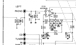
I am trying to solve the crosstalk problem of a Adcom gfp555ii. Looking at the schematic I found that the circuit board is connected to the chassis via a capacitor but there is a 10 ohm resistor which is connected to no where. Is there anything wrong and is it related to the crosstalk problem, i.e. I can hear the music through Tape In when the cd is connected to the CD input?
Attachments
On a schematic all of the signal ground connections are assumed to be at the same potential, but in reality that is not the case. Current cannot flow in a conductor without voltage drop, so wherever current is flowing in a ground, the ground is no longer equipotential.
Common grounding of input connections is a common source of crosstalk between the inputs. Signal return currents flowing in shared grounds means that voltage drops from one channel are shared with other channels.
Getting back to the schematic you've posted, it is obvious that if in fact the input connections have a common ground connection as shown any input with a signal will bleed into all of the other inputs. You can reduce the crosstalk by increasing the size (thickness) of the ground bus, but doubling the conductor (i.e. halving the resistance) will only reduce the crosstalk by a few dB.
Ideally the grounds from each input should be separated at the connectors and only joined together at a star point with the power supply ground and electrical ground, so that no two signal grounds do not share the same current path within the amplifier.
This is a problem of offness - how much the signal switching attenuates the signal from an input that is not currently selected.I can hear the music through Tape In when the cd is connected to the CD input?
Normally an "off" input cannot have any current flowing, so it cannot affect any ground loop. But switches have leakage capacitance allowing signal at higher frequencies to seep across directly to the signal path. 1pF at 10kHz is about 15M impedance, which could be audible if the receiving stage has 50k input impedance levels as this only -50dB of offness (50k is typical input impedance of audio signal path circuitry).
The solution is often just to improve the way inputs are switched so that the "offness" is better than this - perhaps using switches in series with load resistors to ground in-between (forms potential divider with the leakage capacitance).
Reducing the input impedance to 10k or so is often done these days, partly because it helps with offness, partly because it reduces hiss if no input is connected.
BTW the spectrum of the interfering signal will directly indicate if its a capacitance issue or a ground-loop current - the former has a treble boost characteristic of a high pass RC circuit, the latter has a flat frequency response. This should be easy to determine by ear - is the interfering signal tinny sounding? Then its capacitive leakage.
Last edited: