I have the 585- appears to have the leaky cap syndrome-
I found a guy that repairs amps, but he has never worked on this particular one-
its the only chance I 've got- I have explained to him it appears to be a known issue and others have successfully repaired it on this forum. he tells me if I can get him all the info from here he will attack it from there and double check it and use the recommended replacement parts etc.
the trouble is, I do a search for " Adcom-GFA-585, and all I can find is people saying there is plenty of documentation in here about the issue and how to fix it , yet all I can find doing various searches is people talking people out of doing it themselves or "do a search- I am not finding the info he will need to do this successfully. He is experienced and a local Amp repair guy that has worked on literally thousands of other amps-
I prefer to give him info on this exact amp and others successful steps that he can follow, I am even going to let him use my ultrasonic if necessary-
CAN anybody point me to the INFO to give him. I want this done in the typical manner and point him at the success oriented information.
try to keep in mind- I am at this forum because it is DO it yourself and trying to make use of others success as opposed to sending it off to new jersey for 500.00
if it fails and cant get it fixed - who cares- I am willing to take that chance for 125.00 bucks he agreed to do it.
please - I know the risks and I am at the point where it is no good the way it is- so this is the only chance I have or throw it away. it pops when turned on- and voltage is going to the right channel speaker output- and that just started- I know it will be difficult- that is not necessary to mention. I can see everyone thinks this is imposible to repair- its a paperweight right now, and if I gamble 125.00 its worth it. it may end up in the trash I don't care. if it ends up that way. but I want to give them a shot.!
Thanks in advance
Here is a VERY good GFA-585 "leaking capacitor repair" thread, with LOTS of details. Walt Jung, who was a member of the GFA-585 design team, even posted, several times, with some technical info. Good luck.
http://www.diyaudio.com/forums/solid-state/90059-speakers-adcom-gfa-585-a.html
Cheers,
Tom Gootee
http://www.diyaudio.com/forums/solid-state/90059-speakers-adcom-gfa-585-a.html
Cheers,
Tom Gootee
Geeze-
thanks buddy, I have the resources locally to arm someone with necessary info to repair this successfully, couldn't find anything but, "don't do it , you aren't smart enough, send it to me." whats the point of DIY if you aren't afraid to give it a shot. it's mine, if I can't do it - I just find someone that can, no matter how bad it gets. it doesn't function correctly, the most I will do is not fix it- who cares. it's not like it is not been covered before- my boards are barely damaged if at all, I don't even see leakage to be honest, but I thing identifying and replacing them cannot hurt. thats all I wanted to do. after that, maybe find someone to do the adjustments . I don't have a scope anyway =anymore.!
again thanks for pointing me in the right direction!
P
No problem. I have a GFA-585, too. I don't think that mine is leaking yet but I am going to replace the caps.
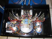
I removed the top cover and with a good light I can see the two small brown-colored ones, installed on their sides, near the rear center of the unit. They're near the rear edges of the two vertically-mounted input boards that are mounted near the middle, in the rear.
I will just replace all of the small electrolytics in the whole unit, while I'm at it.
Good luck,
Tom
For those interested I have Adcom 22,000Uf 100V computer grade
caps at $23.95ea 2 1/2" dia 4 1/8 Tall picture here: http://www.apexjr.com/images/AdcomCap.jpg
caps at $23.95ea 2 1/2" dia 4 1/8 Tall picture here: http://www.apexjr.com/images/AdcomCap.jpg
Following the bouncing ball here...
Ok thanks for the input.
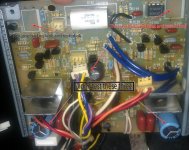
just to be clear, here's a picture with arrows pointing at all the caps on the input board- the two that are missing, I pulled out and tested
Inspection revealed ONE leaky cap- that tested bad, just to be safe -
is everyone basically agreeing that it is just better to replace all the caps - I mean, "all the ones that I have red arrows pointing at?" or just the brown ones?
I bought 8 of the brown 25v 220mF ,which was what was in there originally. that do not exist in the picture here- they were smaller in size, but same imprints on them, - so the guy at the electronics store said they were the same thing just not to worry about the physical appearance-
OR- is there known good ones to replace them all with-
I am not trying to rebuild this amp just get it functioning would be fine, if upgrade is as easy as replacing some parts thats fine I don't want to get into modifying it.
After that, do I send it over to someone to adjust the dc-offset or is that simple enough to do with a meter and a small screwdriver on the pots at the top? or is it possible that won't need any adjustment after replacing caps?
the unit works, its not like it exploded or anything- I' just noticed it had an issue, so here I am.
Ok thanks for the input.
just to be clear, here's a picture with arrows pointing at all the caps on the input board- the two that are missing, I pulled out and tested
Inspection revealed ONE leaky cap- that tested bad, just to be safe -
is everyone basically agreeing that it is just better to replace all the caps - I mean, "all the ones that I have red arrows pointing at?" or just the brown ones?
I bought 8 of the brown 25v 220mF ,which was what was in there originally. that do not exist in the picture here- they were smaller in size, but same imprints on them, - so the guy at the electronics store said they were the same thing just not to worry about the physical appearance-
OR- is there known good ones to replace them all with-
I am not trying to rebuild this amp just get it functioning would be fine, if upgrade is as easy as replacing some parts thats fine I don't want to get into modifying it.
After that, do I send it over to someone to adjust the dc-offset or is that simple enough to do with a meter and a small screwdriver on the pots at the top? or is it possible that won't need any adjustment after replacing caps?
the unit works, its not like it exploded or anything- I' just noticed it had an issue, so here I am.
Attachments
stupid question, but, is this good to have extras of- do these blow up on people regularly?
I might be interested
I might be interested
Yes, just replace all of those. I would also replace all of the other small electrolytic caps, everywhere in the amp, while you're at it.
I would use caps rated for 105 degC instead of 85 degC. Type of caps shouldn't matter too much. I think someone said Panasonic FA would be fine. I'll probably use something like Nichicon UHE series, from mouser.com.
They should not blow up regularly; maybe every twenty or thirty years or so, they will need replacing.
I don't think that replacing the caps alone should require resetting any adjustments.
The main thing is to measure the DC Voltage across each set of speaker terminals. It should go to < 0.030 Volts (30 mV) within ten seconds or so after power on. If it doesn't, then you will need to clean the boards and components per the previously-linked thread.
There is a free downloadable service manual at, I think, HiFi Engine, in case you ever do need to do the adjustments.
Cheers,
Tom
For those interested I have Adcom 22,000Uf 100V computer grade
caps at $23.95ea 2 1/2" dia 4 1/8 Tall picture here: http://www.apexjr.com/images/AdcomCap.jpg
Thanks, Apex Jr. I may do that if I ever get around to testing the ESR of the ones that are in there now. Are yours new? Are they recently manufactured?
Thank you so much for the info- I'll clean the boards just to be safe at this point- you are the man!
Thanks, Apex Jr. I may do that if I ever get around to testing the ESR of the ones that are in there now. Are yours new? Are they recently manufactured?
Manufacturer date is the 49th week of 2001 and new old stock (NOS)
http://www.apexjr.com/images/AdcomCap.jpg
Hi everyone,
Because this is a newer thread I thought I would add in my experience in the repair of the DC offset problem. It's taken me several attempts but I think I got it. I started out removing the electro caps and replacing a few resistors. I also removed a few other parts such as the Bias pot and all metal hardware. I then hand washed the servo boards in a small tub. The leaking caps didn't seem to be that bad. After getting it all back together both channels still had an high DC offset(500mv and 200mv). I was not happy.
2nd attempt 6 or so months later. I removed the servo board with the highest offset(500mv) and removed everything as before, this time including the jumper wires. I placed the PCB in the dishwasher on the top rack. I actually tied it down to make sure it didn't move and ran the washer for two cycles(with soap). Upon removal I used my leaf blower, yes my leaf blower! to blow dry the PCB. I then ran up the oven to 170F(the lowest setting), turned the oven off and hung the PCB inside and let the temp ramp down normally(1 hr). After letting it sit for a few days I rechecked ALL resistors for tolerance and ended up replacing 3 more. Offset after reassembly---->It starts out at 90mv(cold start) and ramps down quickly to less than +-4mv. Ramp time is about 1min.
Success at last! I got the dishwasher idea from the forum. Thank you so much!!
David
Or use Simple Green cleaner diluted about 1 part to 10 parts water. Let the boards soak for about 15 minutes and scrub with a soft nylon acid brush. Rinse well and repeat. I use a hair dryer on low to dry the boards and then let them air dry for at least a day. The capacitor electrolyte is colorless and very difficult to see without a magnifying lamp. The three 220uF electrolytics are the problem and the leaky cap issue applies to the GFA-585 and the GFA-565 monoblocks. Be sure to remove the DC servo IC and clean not only the chip itself (especially underneath and between the pins) but also the dip holes in the pc board.
Repair Update from post# 12:
I pulled the second servo board which had a 200mv offset and completed the wash process previously stated. Offset after re-install is 60mv at turn on which then ramps down to +-3mv within a minute. If I had to do it all over again I would do a pre-soak in a water/Simple Green solution before using the dishwasher. I didn't mention it before but I did replace All electro caps on the output PCB's and on the PS relay board as a precaution. The amp sounds wonderful and I would say the best sounding Adcom amp I have(GFA-6000 & GFA-5503). I've only seen one post mentioning a faint click noise coming from the speakers at turn on/off. Is that normal? Anyway I decided to install one of those speaker protections kits being sold on EBay($15). Has anyone one else done this? It seems too work well and I haven't noticed any problems as of yet. If I had to do this again I would have installed 2 units(one/ch). The relays are rated it 30amps but I would double them to be safe. Oh, no more faint turn on clicks from the speakers....
I have a GFA-5802 lined up for my next project. The left channel output PCB burned up. The whole amp cost me $50.
- Status
- Not open for further replies.
- Home
- Amplifiers
- Solid State
- Adcom GFA-585-known issue guide-Needed