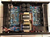
I recently picked up a Adcom GFA-535-II off of Craiglist for $80. I found a service manual for it and have been looking under the hood. I’ve found that the schematic has an error and omission and thought I’d share my findings. I attached the service manual and the schematic extracted from said manual with the errors and omissions highlighted.
The Error
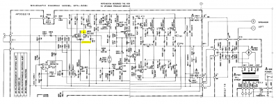
The schematic in the service manual shows to input to the VAS stage coming off of collection the feedback transistor (Q603/Q604) of the LTP. When I first saw this in the service manual schematic I was a bit baffled by the topology. I couldn’t figure out how this could possibly work. I opened up the unit and probed the connections with the continuity setting on my DMM and confirmed the error. The connection should be to the collector of input transistor in the LTP (Q601/Q602 not Q603/604).
The Omission
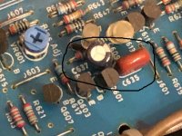
The omission is an electrolytic capacitor C637/638 bypassed by film cap C635/636. These are DC blocked caps in the feedback loop. In my unit (Rev-2 of the PCBs), these caps are mounted on the boards with silk screen and are spec’d at:
I understand there are three versions of this situation:
Other Omissions?
One more item to note… The capacitors in the service manual go to C631/632. The omitted capacitors I found started at C635/C636. This suggests that C633/C634 exist somewhere. However, I could not locate them.
That’s all. I hope someone else finds this information useful.
The Error
The schematic in the service manual shows to input to the VAS stage coming off of collection the feedback transistor (Q603/Q604) of the LTP. When I first saw this in the service manual schematic I was a bit baffled by the topology. I couldn’t figure out how this could possibly work. I opened up the unit and probed the connections with the continuity setting on my DMM and confirmed the error. The connection should be to the collector of input transistor in the LTP (Q601/Q602 not Q603/604).
The Omission
The omission is an electrolytic capacitor C637/638 bypassed by film cap C635/636. These are DC blocked caps in the feedback loop. In my unit (Rev-2 of the PCBs), these caps are mounted on the boards with silk screen and are spec’d at:
- C635/C636: Film 0.47μF 400V
- C637/C638: Electrolytic 22μF 50V
I understand there are three versions of this situation:
- Original with no caps
- Caps installed on the underside of the PCB without silkscreen
- Caps installed on the top side with silkscreen (Rev-2 boards)
Other Omissions?
One more item to note… The capacitors in the service manual go to C631/632. The omitted capacitors I found started at C635/C636. This suggests that C633/C634 exist somewhere. However, I could not locate them.
That’s all. I hope someone else finds this information useful.
Attachments
Hi Brian:
Thank you for taking the time for posting this !
I have 2 stock 535-II's and had been stumped for quite sometime as the schematic/service manual did not completely match the actual boards re C637/C638 & C635/C636. One of the 535-II's was "original with no caps" and the other "Caps installed on the top side with silkscreen".
As I am in the process of rebuilding & recapping these two units, I would be interested in knowing your experience with/without the electrolytic cap bypassed with the film. Also, did increasing C637/C638 to 100uF (low pass 1.6Hz) sound better than factory stock 7.2Hz?
Stay safe
Mayank
PS: I too was unsuccessful in trying to locate the elusive C633/C634 capacitors.
Last edited:
Hi Mayank,
I didn't make any changes to my unit. I was merely speculating that increasing the cap size may improve the sonics. In addition, I believe many users on this board would argue that the bypass caps (C635/C636) aren't necessary. Though they also don't do any harm.
The signal ground issues with the app are probably this biggest areas for improvements. User Phloodpants has these well documented on his site. He offers a new PSU board to address it and improve the PSU, as well as a DIY solution that doesn't involve replacing the PSU board. He also suggests that replacing the input LTP pair with matched BJTs is an improvement.
I'd suggest searching his threads on this forum as well as his site. He has quite a few "overhaul" threads that are an interesting read.