Just completed stuffing the PCB of this kit, so thought I would show some pics, for any interested parties. The link for the kit is here: AD24QS - Audio Analog to Digital Converter 24 Bit / 192 kHz
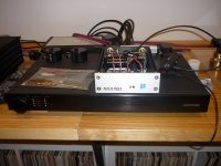
Am currently installing it in a 1RU Modushop case ... so I can't tell you yet, how it sounds. (Or even whether it works! There's a lot of pretty fine soldering involved ... so hopefully I have no dry solder-joints! 🙁 )
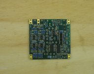
The kit cost me 168 euro, including shipping - which I thought was very reasonable. And Uwe is great to deal with. The PCB is about 90mm square and all components are provided. Uwe also solders 3 surface-mount chips onto the PCB for you - so all you have to do is solder the through-hole components.
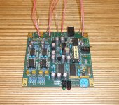
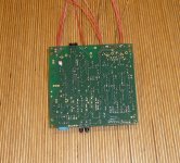
Pic #1 is when all the flat components had been installed. Pic #2 shows the top of the PCB when all the components I required for my build had been soldered in ... and pic #3 shows the underside of the PCB. The wires you can see in pics 2 & 3 are because I didn't use the supplied PCB-mount RCA connectors and the 12v power socket. This was for 2 reasons:
1. IMO, PCB-mount RCA sockets are not up to the quality of the case-mounted RCA sockets that I like to use, and
2. I bought a larger case than the one Uwe recommends, due to the fact that I am sharing the PS for the ADC with 2 other digital components - so I needed space at the back of the case for resistors and caps, to isolate the other 2 DC feeds.
Regards,
Andy
Am currently installing it in a 1RU Modushop case ... so I can't tell you yet, how it sounds. (Or even whether it works! There's a lot of pretty fine soldering involved ... so hopefully I have no dry solder-joints! 🙁 )
The kit cost me 168 euro, including shipping - which I thought was very reasonable. And Uwe is great to deal with. The PCB is about 90mm square and all components are provided. Uwe also solders 3 surface-mount chips onto the PCB for you - so all you have to do is solder the through-hole components.
Pic #1 is when all the flat components had been installed. Pic #2 shows the top of the PCB when all the components I required for my build had been soldered in ... and pic #3 shows the underside of the PCB. The wires you can see in pics 2 & 3 are because I didn't use the supplied PCB-mount RCA connectors and the 12v power socket. This was for 2 reasons:
1. IMO, PCB-mount RCA sockets are not up to the quality of the case-mounted RCA sockets that I like to use, and
2. I bought a larger case than the one Uwe recommends, due to the fact that I am sharing the PS for the ADC with 2 other digital components - so I needed space at the back of the case for resistors and caps, to isolate the other 2 DC feeds.
Regards,
Andy
Attachments
This is a decent set of kit, I ended up modding mine to take bipolar 12VDC (which eliminates the negative supply inverter) and added a buffer for the biasing current to accommodate Sparko discrete opamps.
Uwe is awesome to deal with, couldn't ask for better. You might be interested in the SPDIF to USB. Pics of mine are in my signature link TT2USB.
Uwe is awesome to deal with, couldn't ask for better. You might be interested in the SPDIF to USB. Pics of mine are in my signature link TT2USB.
I should also add that the input of this ADC is actually fully balanced if you wire it as such. The stock config converts the input to RCA. This makes it very good value for anyone requiring balanced inputs.
- Status
- Not open for further replies.