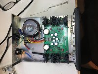
Well I haven't posted for a while so I thought I'd share my latest project of rebuilding an Acurus RL-11. I rebuilt an A-150 a while back and I was looking to find a RL-11 to match it, and honestly I just can't live without remote volume anymore :=) so the RL-11 was my only option in the Acurus line.
So some of the improvements I saw that could be made were in the power supply for the preamp section, maybe improve the circuitry a bit, and the volume control on this unit had seen better days so it needed replacing.
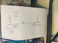
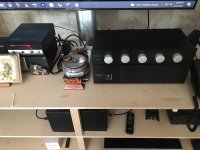
The biggest problem I see with this preamps power supply is that the transformer is undersized, the regulator for the preamp looks pretty good and it is mostly separate from the volume control voltage. The only place where they are tied together is for the relay that ungrounds and mutes the input signal. I had an parallel regulated power supply already so I decided to go a bit overboard on it but I would of been happy with just upgrading the transformer if I didn't already have the supply. So I put the parallel regulator and a 25 VA transformer in a case I had from an old frequency counter and used XLR jacks to connect it to the preamp. I tried to match the old voltage of 17.5-0-17.5 volts as closely as possible.
So some of the improvements I saw that could be made were in the power supply for the preamp section, maybe improve the circuitry a bit, and the volume control on this unit had seen better days so it needed replacing.
The biggest problem I see with this preamps power supply is that the transformer is undersized, the regulator for the preamp looks pretty good and it is mostly separate from the volume control voltage. The only place where they are tied together is for the relay that ungrounds and mutes the input signal. I had an parallel regulated power supply already so I decided to go a bit overboard on it but I would of been happy with just upgrading the transformer if I didn't already have the supply. So I put the parallel regulator and a 25 VA transformer in a case I had from an old frequency counter and used XLR jacks to connect it to the preamp. I tried to match the old voltage of 17.5-0-17.5 volts as closely as possible.
Attachments

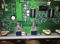
I removed the preamps internal regulator to allow for a few extra filter caps I wanted to add. I added 2200uF electrolytic and 10uF polypropylene caps across each voltage rail and added some .1uF cog caps on the underside of the PCB to each side of the power rails.
Attachments
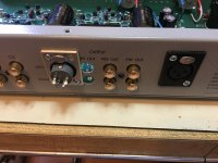
also I wanted to be able to bypass the output capacitors for when my power amp is capacitively coupled. This is a feature I've always wanted on an analog preamp and I had a 4 pole XLR so I used this to create a jumper that could be added or removed based on the power amp I'm using. I also upgraded the output caps to Solen polypropylene.
Attachments

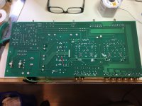
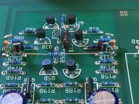
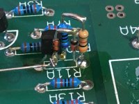
When comparing the RL-11 circuit to some of Mondial's higher end stuff the addition of current sources in place of the emitter resistors on the input differential pair was the most stark improvement I could see. So I found there was 17 volts dropped on the emitter resistor of 61K, this gives about 200 uA. I used BC550, 560 with 1N4148 signal diodes to create the needed current source.
they were a bit tricky to make so they would fit into the space of the resistor but with a bit of practice it worked.
they were a bit tricky to make so they would fit into the space of the resistor but with a bit of practice it worked.
Attachments
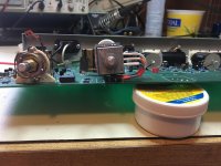
and finally the volume needed to be replaced on this unit. I'm guessing my preamp is over 20 years old and had seen a lot of use. The volume control was grinding pretty good when activated. the problem is that Acurus used a very unique height volume pot and the standard replacement wasn't going to fit if I soldered it directly to the PCB. so I just made a kind of umbilical and turned it on it's side and it seemed to fit quite well. One thing is I disconnected the balance control and bypassed it. I removed the balance pot and did some measurements on it and I'm sorry to say but it's tracking was WAY off. Like thousands of ohms off. So I didn't really need it anyways because I have a room correction processor. so I just bypassed it and turned it sideways so I could still put the knob on the front.
because the balance is bypassed I wanted to still preserve the correct input impedance for this preamp (which is 10 K ohms apr.) So I replaced the 22k existing pot with a 10 k pot. about the only hiccup I ran into when doing this rebuild was at first I didn't realize that the mute relay relied on the negative voltage rail that supplied the preamp section. so when I first fired it up I could measure that everything was good but I could not get any sound. It baffled me until I took a closer look at the relay and saw the tie in to the parts I had pulled, so I just recreated the negative rail in a diminished capacity to satisfy the relays need.
because the balance is bypassed I wanted to still preserve the correct input impedance for this preamp (which is 10 K ohms apr.) So I replaced the 22k existing pot with a 10 k pot. about the only hiccup I ran into when doing this rebuild was at first I didn't realize that the mute relay relied on the negative voltage rail that supplied the preamp section. so when I first fired it up I could measure that everything was good but I could not get any sound. It baffled me until I took a closer look at the relay and saw the tie in to the parts I had pulled, so I just recreated the negative rail in a diminished capacity to satisfy the relays need.
Attachments

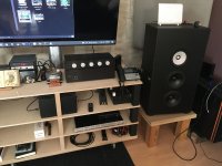
how does it sound, well... WOW! What an improvement. It's like the sound on some material just completely detaches from the speaker position and an amazing sonic image is created for the listener. It is very detailed and has tons of slam in the bottom end. It just seems to reach into the lower octaves with much more authority. I've done all my listening with the output capacitors bypassed. With the new Alps volume pot in place operation is whisper quiet. I'm not really sure which improvement has done the most for the sound because I redid it all at once. These upgrades are highly recommended for the more pragmatic audiophile. I mean I could have chosen to upgrade the connectors on the back and you can spend a ton of money there these days but I wanted to spend the money and time where I knew (read scientifically) an appreciable electrical difference would be detectable. The parallel regulated power supply really brought the noise floor down some more and the umbilical is done with fully shielded cable.
Attachments
Nice work
Hi Buddy I managed to sign up wow nice work beautiful soldering job and upgrade of components I wish you lived closer to hang out and learn a few things keep me posted on any future projects cheers
Hi Buddy I managed to sign up wow nice work beautiful soldering job and upgrade of components I wish you lived closer to hang out and learn a few things keep me posted on any future projects cheers
Hi there -- ive just picked up today an RL-11 , i wonder if you could steer me in the right direction ? --- it will not power up !! nothing happens when i turn the power control knob -- ive got only as far as testing there is 240v across the internal fuse and yes there is - i guess i need to access the power switch solder points but not yet pulled the board out for that - any pointers you may have i would really appreciate ---- Chrishow does it sound, well... WOW! What an improvement. It's like the sound on some material just completely detaches from the speaker position and an amazing sonic image is created for the listener. It is very detailed and has tons of slam in the bottom end. It just seems to reach into the lower octaves with much more authority. I've done all my listening with the output capacitors bypassed. With the new Alps volume pot in place operation is whisper quiet. I'm not really sure which improvement has done the most for the sound because I redid it all at once. These upgrades are highly recommended for the more pragmatic audiophile. I mean I could have chosen to upgrade the connectors on the back and you can spend a ton of money there these days but I wanted to spend the money and time where I knew (read scientifically) an appreciable electrical difference would be detectable. The parallel regulated power supply really brought the noise floor down some more and the umbilical is done with fully shielded cable.
Welcome.
Should be zero volts across the fuse. 240V across the transformer primary. If this is not clear, be very careful. 240V can be deadly.testing there is 240v across the internal fuse
what i meant was with the IEC plugged in i get voltage across the mains fuse - im hoping the switch hasn't failed as i doubt i could find one , i wonder if the K1 positioned 24v relay has failed ? i think reading above it does interact with the power switch mute circuit - i need to pull the board out to further find out why it will not power up and fuse is intact -- no schematic can be found !!Welcome.
Should be zero volts across the fuse. 240V across the transformer primary. If this is not clear, be very careful. 240V can be deadly.
many thanks - this might help me trace the issue
- Home
- Source & Line
- Analog Line Level
- Acurus RL-11 rebuild