Hello... I haven't been around for a while but I thought I'd share my last project with everyone.
I bought an Acurus A150 about a year and a half ago and I've been using it since. since i got it I had the itch to upgrade it because I felt it had a lot of potential but was being held back because of some shortfalls. First off this is a very old A150, the heatsink is half the size of every other one I've ever seen. the only time I've seen one with a heatsink this small was on an article reviewing this amp when it was first released. I don't have a problem with this because my speakers are very efficient 8 ohms and I don't need more then 50 watts to really make them sing. also the device bonding surface of the heatsink is really rough. thousands of small grooves that should have been polished out but weren't, oh well.
the voltages rails on this amp are 77-0-77 with 120 volt AC and the main filter caps are rated for 80 volts! that is not a very comfortable margin for my tastes. The transformer is excellently balanced, when dc is made the rails are only 1 mv out from each other! that's a nice tight margin. the fact that this amp has lived 30 years and kept working is a bit of a wonder. recently I opened the amp and saw that a zener diode and small signal transistor were destroyed, literally split in half and the damn amp was still making music with little dc offset on the output. that's pretty amazing. it looks like it had been in this condition for many years.
okay so now to the refurbish and upgrading.
2sa1349GR replaced with 2sa1349BL
2sc3381GR replaced with 2sc3381BL
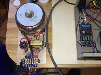
these are the input transistors and the stock transistors have between 200 to 400 gain the replacement are 350 to 700 gain. this is a LTP input and increasing the gain on these transistors isn't going to affect the gain of the amp but will make it far more sensitive to small signal detail and I feel just overall improve the sound of the amp. Of corse with the way the transformer is orientated to the vertical pcb using these ment I need to put the transformer outside the amp. I tried it with the transformer in the amp and with my sensitive speakers it just picked up way too much emi and such.
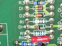
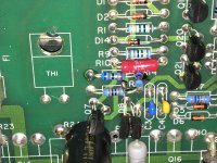
r10 and r12 are part of a cascode circuit (i think) and drop whatever isn't in the 12v zener diode
stock 22k 1/4 watt (pushed right to the limit! at about .2 watt) replaced with 1 watt 22k metal film.
r1 and r8 are part of a current source circuit
stock 390 1/4 watt replaced with 330 .6 watt metal film
I replace all the mpsa92 and mpsa42 with new ones
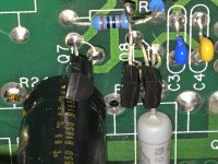
C4,5 changed from 39pf to 200pf cog type ceramic
c10 220pf changed to cog type
1k bias trim pot changed to sealed multi-turn
the ztx757, ztx657 were ganged up with their own emitter resistors which were changed from 47 ohms to 68 ohms on each transistor
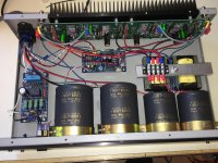
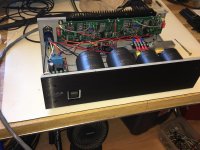
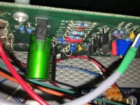
when I first got this amp open I said darn there is a lot of space in there, so I knew I could stuff lots in. so I added a DIY audio soft start and speaker protection unit.
I guess the star of the show is really the powersupply now though. I had had some 3 mH 10 amp e-core inductors kicking around for quite some time now and this was my chance to use them.
22,000uF @80volts changed to 22,000uF @100 volts then the 3mH inductor and then a 15,000uF @100 volts.
I added post fuse capacitors 220uf @100volts and new bipolar caps on the feedback loop. as well new bipolar on the input. when I doubled up the ztx transistors I added a 10 pf miller effect cog cap to the underside of the pcb (basically I copied the A250 schematic).
because I don't need much power and my heatsink is so small and poor I made a decision to remove 2 output transistors per channel and that made adding the post fuse caps super easy.
input jacks changed to cardas rca's
I installed the new cap brackets with rivets so I had to use small spacers when I put the front plate back on to accommodate them.
rebuilt the power swich with a superbright white led and connected it to the protection indicator on the diy audio speaker protector so it flashes when first turned on or when the speaker protection kicks in
because the surface of the heatsink is so rough I didn't feel regular heat sink pads would do it so I went back to heat sink paste and insulators. I know they are not in right now but I needed to fill in all those tiny grooves and thats what was originally used so it felt safer.
A there you go, that's puppies totally rebuilt
so how does it sound, wow!!!
it is super quiet and sounds so clean and effortless. I find myself turning it up and just marveling at the impact I'm hearing. the detail and clarity are just astounding especially on good recordings. this is an amp that really is going to show the source material and capabilities of the rest of your system. I am totally pleased with my work and with the end result. I can't believe there is this much to be had from a quality class a/b amp. I can see why this amp is such a popular rebuild recipient. I bought the amp for $350 Canadian and I put about $350 into it. I think there's about 50 hours labour but then again I had to rework some stuff to get it to where I needed it to be.
I've tried to explain my upgrades as well as possible and I do not understand everything about the circuit so if I've gotten one or two things wrong please forgive a home diy enthusiast.
I bought an Acurus A150 about a year and a half ago and I've been using it since. since i got it I had the itch to upgrade it because I felt it had a lot of potential but was being held back because of some shortfalls. First off this is a very old A150, the heatsink is half the size of every other one I've ever seen. the only time I've seen one with a heatsink this small was on an article reviewing this amp when it was first released. I don't have a problem with this because my speakers are very efficient 8 ohms and I don't need more then 50 watts to really make them sing. also the device bonding surface of the heatsink is really rough. thousands of small grooves that should have been polished out but weren't, oh well.
the voltages rails on this amp are 77-0-77 with 120 volt AC and the main filter caps are rated for 80 volts! that is not a very comfortable margin for my tastes. The transformer is excellently balanced, when dc is made the rails are only 1 mv out from each other! that's a nice tight margin. the fact that this amp has lived 30 years and kept working is a bit of a wonder. recently I opened the amp and saw that a zener diode and small signal transistor were destroyed, literally split in half and the damn amp was still making music with little dc offset on the output. that's pretty amazing. it looks like it had been in this condition for many years.
okay so now to the refurbish and upgrading.
2sa1349GR replaced with 2sa1349BL
2sc3381GR replaced with 2sc3381BL
these are the input transistors and the stock transistors have between 200 to 400 gain the replacement are 350 to 700 gain. this is a LTP input and increasing the gain on these transistors isn't going to affect the gain of the amp but will make it far more sensitive to small signal detail and I feel just overall improve the sound of the amp. Of corse with the way the transformer is orientated to the vertical pcb using these ment I need to put the transformer outside the amp. I tried it with the transformer in the amp and with my sensitive speakers it just picked up way too much emi and such.
r10 and r12 are part of a cascode circuit (i think) and drop whatever isn't in the 12v zener diode
stock 22k 1/4 watt (pushed right to the limit! at about .2 watt) replaced with 1 watt 22k metal film.
r1 and r8 are part of a current source circuit
stock 390 1/4 watt replaced with 330 .6 watt metal film
I replace all the mpsa92 and mpsa42 with new ones
C4,5 changed from 39pf to 200pf cog type ceramic
c10 220pf changed to cog type
1k bias trim pot changed to sealed multi-turn
the ztx757, ztx657 were ganged up with their own emitter resistors which were changed from 47 ohms to 68 ohms on each transistor
when I first got this amp open I said darn there is a lot of space in there, so I knew I could stuff lots in. so I added a DIY audio soft start and speaker protection unit.
I guess the star of the show is really the powersupply now though. I had had some 3 mH 10 amp e-core inductors kicking around for quite some time now and this was my chance to use them.
22,000uF @80volts changed to 22,000uF @100 volts then the 3mH inductor and then a 15,000uF @100 volts.
I added post fuse capacitors 220uf @100volts and new bipolar caps on the feedback loop. as well new bipolar on the input. when I doubled up the ztx transistors I added a 10 pf miller effect cog cap to the underside of the pcb (basically I copied the A250 schematic).
because I don't need much power and my heatsink is so small and poor I made a decision to remove 2 output transistors per channel and that made adding the post fuse caps super easy.
input jacks changed to cardas rca's
I installed the new cap brackets with rivets so I had to use small spacers when I put the front plate back on to accommodate them.
rebuilt the power swich with a superbright white led and connected it to the protection indicator on the diy audio speaker protector so it flashes when first turned on or when the speaker protection kicks in
because the surface of the heatsink is so rough I didn't feel regular heat sink pads would do it so I went back to heat sink paste and insulators. I know they are not in right now but I needed to fill in all those tiny grooves and thats what was originally used so it felt safer.
A there you go, that's puppies totally rebuilt
so how does it sound, wow!!!
it is super quiet and sounds so clean and effortless. I find myself turning it up and just marveling at the impact I'm hearing. the detail and clarity are just astounding especially on good recordings. this is an amp that really is going to show the source material and capabilities of the rest of your system. I am totally pleased with my work and with the end result. I can't believe there is this much to be had from a quality class a/b amp. I can see why this amp is such a popular rebuild recipient. I bought the amp for $350 Canadian and I put about $350 into it. I think there's about 50 hours labour but then again I had to rework some stuff to get it to where I needed it to be.
I've tried to explain my upgrades as well as possible and I do not understand everything about the circuit so if I've gotten one or two things wrong please forgive a home diy enthusiast.
Attachments
-
 IMG_0669.jpg989.8 KB · Views: 1,025
 -
 IMG_0671.jpg821.9 KB · Views: 604
 -
 IMG_0670.jpg991.9 KB · Views: 402
 -
 IMG_0668.jpg795.4 KB · Views: 429
 -
 IMG_0677.jpg717.4 KB · Views: 410
 -
 IMG_0676.jpg636.3 KB · Views: 326
 -
 IMG_0674.jpg986 KB · Views: 336
 -
 IMG_0680.jpg878.1 KB · Views: 329
 -
 IMG_0675.jpg935.2 KB · Views: 424
Last edited: