The method of displacing the membrane by putting weights on the dust cap and reading the displacement is described in this thread: http://www.diyaudio.com/forums/showthread.php?s=&threadid=8055
The weights here were small chai-tea glasses and spools of solder.
For motor measurements, I used the very same setup. Current came from a battery pack charger with an estimated output resitance of 10 R. I then used 3R9 / 5W resistors to obtain three different currents by using one or two resistors in series or by paralleling them. The combined current resistance of supply and these resistors was enough to keep the current constant regardsless of VC temperature. In fact, currents between 3 and 6 R voice coils different by less than 5%.
The first driver measured was an 8" device salvaged from a 10-year old, midprice T+A PP160 speaker. It is must be a Vifa (telling from the basket and the label), even if it does not use the brand name. Spider is flat, surround is foam (still intact).
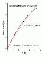
A straight linear fit would tell me I had problems reading the zero position. However, the fit becomes a lot better if we assume I got that right but there is some nonlinearity in the suspension. This is what is called a progressive suspension, i.e. for very large excursions, the suspensions begins to limit, preventing damage and partly compensating the motor nonlinearity. The motor force becomes larger as the voice coil leaves the gap partly, even if this is not what one would expect intuitively.
By the way, I obtained the force from the weights by taking the mass in g. dividing by 1000 and multiplying by 9.807 N/kg to obtain N.
Eric
By the way, I obtained the force from the weights by taking the mass in g. dividing by 1000 and multiplying by 9.807 N/kg to obtain N.
Eric
motor strength
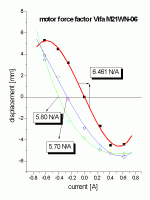
Next, I applied three different currents. The red curve is without an extra weight. A polynomial third order fit gives a nice result (red curve). The linear excursion range is +/- 4.5 mm (sorry, I don't have the geometrical data on VC and gap).
From the slope around 0 A, I obtain the mm/A. Dividing this by the compliance gives me the motor strength in N/A.
The blue and green curves are for an added mass of 154 and 236 g. Clearly, the slopes at 0 A are still similar to the red curve, so the motor still seems to be linear, but in the lower right hand corner we can see that the suspension limits further excursion.
The force factor can also be calculated by converting the mass to N and looking what kind of a current would be necessary according to the fit curves to move the cone back to X=0. Agreement with the value obtained from the slope of the red curve is good, considering that the blue and green fit do not describe the data points perfectly.
Attachments
- Status
- Not open for further replies.

