I have this xover and want to add some EQ. A notch filter centered on 2kHz with 3dB of cut, and baffle step comp. for a 300mm wide cabinet. Can anyone advise?
I will post more details later.http://www.diyaudio.com/forums/gallery/data/1733/xover_schematic_22.png
I will post more details later.http://www.diyaudio.com/forums/gallery/data/1733/xover_schematic_22.png
Last edited:
nope
may be caused by enlarging before uploading
anyway, you will find some curcuit describtions on ESP site
look in the Crossovers and Effects section, and also in the Musical Instrument section
may be caused by enlarging before uploading
anyway, you will find some curcuit describtions on ESP site
look in the Crossovers and Effects section, and also in the Musical Instrument section
Fixt. I'll give more details tomorrow. I've looked on the ESP site and still need help!
Last edited:
If those are XLR connectors, they're connected very non-standard. Beware of compatability. Or maybe it's just typos.
All good fortune,
Chris
All good fortune,
Chris
I find puzzling things in this schematic, such as 1. an inverting input buffer that lowers input signal to about 1/7th , with the non-inverting input connected to ground through a noise generating 2,7Kohm, 2. + and - have been reversed in the drawing for the filter opamps. It is the topology of a VCVS filter, which is a bandpass configuration. I don't think it will even work. 3. Why capacitive coupling to the output buffers? Input is already decoupled.
Perhaps you can visit Sigfried Linkwitz' site, where you can learn a lot about designing Sallen-Key filter based xovers, which are guaranteed to work.
vac
Perhaps you can visit Sigfried Linkwitz' site, where you can learn a lot about designing Sallen-Key filter based xovers, which are guaranteed to work.
vac
They are typos. I don't know how to change them in TinyCad, which is were I drew this. I am not very good with computers, and this is my first attempt to post a schematic.If those are XLR connectors, they're connected very non-standard. Beware of compatability. Or maybe it's just typos.
All good fortune,
Chris
You are correct, + and - are the wrong way round. Please be patient with me, as I am struggling to use the CAD programme, and I can't put things in the way I want to. I used an opamp symbol, but must have picked the wrong one!I find puzzling things in this schematic, such as 1. an inverting input buffer that lowers input signal to about 1/7th , with the non-inverting input connected to ground through a noise generating 2,7Kohm, 2. + and - have been reversed in the drawing for the filter opamps. It is the topology of a VCVS filter, which is a bandpass configuration. I don't think it will even work. 3. Why capacitive coupling to the output buffers? Input is already decoupled.
Perhaps you can visit Sigfried Linkwitz' site, where you can learn a lot about designing Sallen-Key filter based xovers, which are guaranteed to work.
vac
This design does work, I have been using it on and off since 1982 as a 2 way, but I have only just added the 2 MF circuits. The new 4 way setup is installed in it's case, so I don't want to start again! Everything is to Ben Duncan's original specs. with some updates, such as the Linkwitz alignment resistors for the MF1 and MF2 bandpass filters. I will only be using MF2 for the midrange.
Originally there were also caps after the output buffer opamps, but they have been cut. I wasn't sure if it would be safe to also remove the caps before the buffers.
I am fine making speaker cabs, casework, etc, but the electronic calculations give me a headache! Which is why I need help.
The input buffer attenuatiion was explained in the original notes as compensating for the gain later on. I hope that makes sense, as I am just following a published design (HiFi News March 1981).
What I am hoping to do is add is an equalising circuit, perhaps like the ESP Constant Q Graphic Equaliser project#75, before the attenuator pots. Also if possible I would like to stick with the AD825 opamp, as long as it is stable in this configuration, as I find I like the sound of them. Of course, I am open to advice on that.
I realise I am asking quite a lot, but I just don't have the expertise myself.
Also I want to add baffle step compensation, perhaps a simple circuit like the ESP design, which I hope could be added after the output buffer opamp. That is less important at the moment, as it could be added to the speaker as a passive.
I will try to add pics or diagrams if I can work out how.http://i1134.photobucket.com/albums/m604/awkwardbydesign/Untitled.jpg http://i1134.photobucket.com/albums/m604/awkwardbydesign/oracleparts011.jpg
Last edited:
Don't understand, what does "IP" mean? I edited the first post to make the schematic readable, is that what you mean? Or have I accidently deleted something else? I don't think I posted a different layout, but I AM struggling to get the images posted. Sorry about that, I realise I am not making it easy for anyone who might want to help, and I can only get to the computer occasionally.Has the schematic posted before been deleted because of IP?
IP=intellectual property, but I found it under the link, my mistake.
I took another look at the schematic, and I think it will be unnecessarily noisy. Under this link you will find everything you need to know to do it in a better way: Active Filters
The basic problem in the setup you posted is that in the input stage Vin is reduced, and subsequently re-amplified again in the filter stages. About this input buffer: most audio opamps are unity stable, that is, they will not oscillate if gain=1. I have never used an opamp to give a gain lower than 1, because I always thought this could lead to stability issues. Dunno for sure, but better to prevent it.
XLR in balanced impedance connections
The non-inverted input is PIN1 & PIN2, if not balanced (unbal). PIN1 is the audio ground in this unbal case.
If balanced then the extra PIN3 becomes the inverted input. Thus PIN2 = Hot = non-inverted and PIN3 = Cold = inverted. This time PIN1 is chassis, not audio ground.
The non-inverted input is PIN1 & PIN2, if not balanced (unbal). PIN1 is the audio ground in this unbal case.
If balanced then the extra PIN3 becomes the inverted input. Thus PIN2 = Hot = non-inverted and PIN3 = Cold = inverted. This time PIN1 is chassis, not audio ground.
Thanks, but I already have the xover, I just want to add a notch filter. I understand there may be better circuits, but this is what I have, and I don't have the time or mental energy to start over!IP=intellectual property, but I found it under the link, my mistake.
I took another look at the schematic, and I think it will be unnecessarily noisy. Under this link you will find everything you need to know to do it in a better way: Active Filters
The basic problem in the setup you posted is that in the input stage Vin is reduced, and subsequently re-amplified again in the filter stages. About this input buffer: most audio opamps are unity stable, that is, they will not oscillate if gain=1. I have never used an opamp to give a gain lower than 1, because I always thought this could lead to stability issues. Dunno for sure, but better to prevent it.
That is what I have. The problem is my inability to alter the drawing! It seems I will have to draw my own symbol, but don't yet know how to. The xover DOES work, it's my ability to post that doesn't.The non-inverted input is PIN1 & PIN2, if not balanced (unbal). PIN1 is the audio ground in this unbal case.
Ok, this is the speaker, and I want to cut the shallow peak at 2kHz. If I have a circuit for that, with variable cut, then I should be able to recalculate for different frequencies. But I need help with the original design.
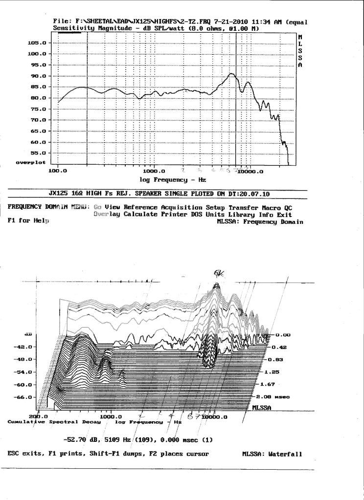
I plan to put the xover point at 4kHz with 24dB slope, so the 6kHz peak will be tamed to some extent. Anyway, that is on-axis, and I will toe them in to suit.
I plan to put the xover point at 4kHz with 24dB slope, so the 6kHz peak will be tamed to some extent. Anyway, that is on-axis, and I will toe them in to suit.
Hi Awkard,
I would go quite a bit lower than 4Khz for xover, more like 2-ish, depending on the tweeter you are using. What is the manufacturers recommendation?
I would go quite a bit lower than 4Khz for xover, more like 2-ish, depending on the tweeter you are using. What is the manufacturers recommendation?
Are you suggesting that because of the 6kHz peak? I can alter the xover point any time I like, but a notch filter would let me play around. Any way, I may change the midrange driver for a different wide range unit. Maybe the L. Cao 8".
At the moment the HF driver is the Jordan JXR6HD, but I also have a Shackman electrostatic panel to try. So I want to make the xover more versatile before I go 3 way.
At the moment the HF driver is the Jordan JXR6HD, but I also have a Shackman electrostatic panel to try. So I want to make the xover more versatile before I go 3 way.
Yes, I prefer to stay away 2 octaves from a break up peak like that, so that would give you even less. Anyways, slipped my mind you are designing a 3 way, so that means there should be no problem. You would cross over the bass driver not any higher than 500 Hz to the mid anyways, and than mid to high somewhere between 2 and 3 Khz.
Bass/mid crossover point is 134Hz at the moment. KEF B139s in isobaric configuration, they break up at just above 400Hz, so low xover point.Yes, I prefer to stay away 2 octaves from a break up peak like that, so that would give you even less. Anyways, slipped my mind you are designing a 3 way, so that means there should be no problem. You would cross over the bass driver not any higher than 500 Hz to the mid anyways, and than mid to high somewhere between 2 and 3 Khz.
I still need the help with a (preferably) single opamp notch filter design. I have NE5534s, OPA132s, OPA604s, AD825s and OPA627s. In the xover itself, I prefer the sound of the AD825s, so would like to stay with them if possible.
As for the Jordan JX125s, the 6kHz peak is on axis, the same as the JX92s, so toeing in sharply minimises that. Anyway, the 24dB/octave slope will also reduce it effect on the sound. I appreciate your good advice, but that is something to consider another time. I want to keep the xover point as high possible at the moment, I may change that at a later date, but not now.
Linkwitz's site doesn't really help me, I don't have the skill to make use of it, I am more a hand/eye type of person, so although MAKING the circuit is not a problem, working it out is. I have made valve preamps (Croft, Concordant, Paragon) by measuring and copying, they worked fine. But if they developed faults, I was in trouble, no theoretical knowledge.
- Status
- Not open for further replies.
- Home
- Source & Line
- Analog Line Level
- Active xover help.