Hi,
i have Acoustat 3, think that is the medalion model MK121C
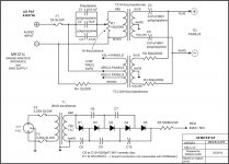
i want to replace the capacitors and the voltage multiplier & if is possible to improve the xover.
this is the schematic i have, there is any thing that could be done better
thanks for your time
best regards
williams
i have Acoustat 3, think that is the medalion model MK121C
i want to replace the capacitors and the voltage multiplier & if is possible to improve the xover.
this is the schematic i have, there is any thing that could be done better
thanks for your time
best regards
williams
Attachments
the caps in the multiplier? sure. NPO, high voltage type.
There is a suggested change to the level control wiring -think it has been posted, search?
The HV coupling caps are hard to beat. Also been discussed...
I got rid of the speaker fuse - you may not wish to defeat this.
_-_-bear
There is a suggested change to the level control wiring -think it has been posted, search?
The HV coupling caps are hard to beat. Also been discussed...
I got rid of the speaker fuse - you may not wish to defeat this.
_-_-bear
hi,
thanks bear,
what do you mean by control wiring, the rheostat for the highs?
i want to replace it by two resistors, do you know the best setting-values?
the 0.01uF/6KV i can get ceramic caps. are good for it?
williams
thanks bear,
what do you mean by control wiring, the rheostat for the highs?
i want to replace it by two resistors, do you know the best setting-values?
the 0.01uF/6KV i can get ceramic caps. are good for it?
williams
the 0.01uF/6KV i can get ceramic caps. are good for it?
You might contact Moray James as he sells Polypropylene caps to replace the Acoustat Polyester caps with the proper AC voltage rating.
There are some more details about these capacitors in his posting here:
http://www.diyaudio.com/forums/plan...-1-high-sound-level-limits-2.html#post2440837
Yes, I meant the big "pot" for HF level setting.
There is another way to wire it, might be better...
The HV caps, if the ufd value is about the same, sure... higher voltage yields a longer life.
But the life stock is >20yrs now...
_-_-bear
There is another way to wire it, might be better...
The HV caps, if the ufd value is about the same, sure... higher voltage yields a longer life.
But the life stock is >20yrs now...
_-_-bear
If your interface was built (or upgraded) to the 'C' version, you have the latest and greatest configuration of the xover network. Replacing the variable resistor with fixed resistors is not a bad idea, esp. since the variable control is subject to corrosion. There is no 'correct' value - that's why it's variable. Find a setting you like, and then replace the two parts with 50-watt fixed resistors - it's just a voltage divider across the HF transformer. You might also consider changing out the 47-uF electrolytic to a polypropylene type - this is probably the most significant change you can make.
I doubt there is much (if any) sonic advantage to replacing the HV multiplier caps. Ceramic discs are a good choice here. I would leave those alone.
If your interface contains 0.01-uF 6kV polypropylene coupling caps (and they almost certainly do - that's all that Acoustat used in these interfaces) then you have the best type for the job. Unless you are having problems, I would leave those alone as well.
With all due respects to AcoustatAnswerMan... btw do you have a super hero cape? 😀
The HV ceramics are likely at the end of their useful life.
I've had to repair a fair number of interfaces whose caps got very leaky, and also may have caused the early demise of the HV diodes. So I would highly recommend the highest breakdown voltage NPO type HV ceramic caps you can find for that slot... the exact value is non critical as long as it is close to the original ufd value. So, imo, a good idea to replace them since it's inexpensive to do so. Just make sure the supply is off and bled down before proceeding.
_-_-bear
My intention in suggesting that the HV multiplier caps needn't be replaced was that there is no point in upgrading them to a different type of capacitor. Certainly, if there is any suspicion that they are failing, or if you just want to make sure, then there is no harm in replacing them with the same or similar type of capacitor.
As for the super hero cape, yes, I DO have one, with a big 'A' on it for Acoustat. I feel extremely priviledged to have worked with Jim Strickland at Acoustat, and get a lot of satisfaction from continuing to help Acoustat owners maintain their speakers. Very few speakers, ESL or otherwise, can boast of the continued good performance and reliability that Acoustats exhibit so many years after manufacture.
And thank YOU Bear, for your continued support and inspiration.😛
Goody, glad you got the official cape! 😀
Wonder which color you got?
I only have a junior AAM cape, myself... a little small when I put it on, but still...
_-_-bear
Wonder which color you got?
I only have a junior AAM cape, myself... a little small when I put it on, but still...
_-_-bear
hi all,
For the connection of the panels, I have four pieces of ceramic 0.01uF 10KV, I think designed for use in high voltage & high freq, size 75x35x4 mm flat profile wrapped in yellow plastic film, can not clearly read the brand name,
Is better capa polypropylene then ceramics for application in acoustat?
ceramic sure better in higher frequencies, but here for this application I'm not sure
Best regards
Williams
hi all,
For the connection of the panels, I have four pieces of ceramic 0.01uF 10KV, I think designed for use in high voltage & high freq, size 75x35x4 mm flat profile wrapped in yellow plastic film, can not clearly read the brand name,
Is better capa polypropylene then ceramics for application in acoustat?
ceramic sure better in higher frequencies, but here for this application I'm not sure
For this application, polypropylene capacitors will work better than all ceramics except perhaps the NP0/C0G types. In this application coupling AC voltage in a crossover, the voltage across the capacitor varies with frequency and most ceramic capacitors change value depending on applied voltage and temperature. Ceramics also tend to have relatively high DA(dielectric absorption) so they will be heating up when you turn up the volume. Poor distortion performance and piezoelectric problems are further reasons to avoid ceramics for audio coupling, except the NP0/C0G type.
NP0/C0G ceramics are generally only available in smaller capacitance values at higher voltage ratings > 1kV.
hi all,
For the connection of the panels, I have four pieces of ceramic 0.01uF 10KV, I think designed for use in high voltage & high freq, size 75x35x4 mm flat profile wrapped in yellow plastic film, can not clearly read the brand name,
Is better capa polypropylene then ceramics for application in acoustat?
ceramic sure better in higher frequencies, but here for this application I'm not sure
Best regards
Williams
Ceramic capacitors are preferred for the High Voltage multiplier, but for all other applications, like the .01-uF coupling caps, or caps in the HF transformer's crossover, polypropylene is the dielectric of choice. Generally, capacitors that are film-n-foil are preferred over metallized film, but one doesn't always have a choice, especially for the high-voltage parts that are already difficult to find.
Acoustat used polypropylene for the .01-uF in all speakers made in the later years. The crossover caps were a combination of an electrolytic bypassed with a smaller-value polypropylene, sometimes further bypassed by an even-smaller polystyrene. Replacing the electrolytic in the crossover with a polypropylene is probably the most effective upgrade that can be done to the speaker.
hi all,
your guys saved me a lot of money and work
i will replace the capas for the hifreq pattern only, 47, 10 and 0.01 uF
i will order SOLEN polypropylene and the small polystyrene set.
i ordered the caps for high voltage multiplier, 0.01uF 3KV ceramic disc .
i am sure it will work fine, these speakers are devine, love the sound
best regards
and a nice weekend,
williams
Hi,
I opened the acoustat interface boxes and found
1 - Model MK-121B medallion, not MK-121C
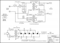
2 - there is a change in hi freq path, it's not the original circuit, as shown in the scheme attached, two resistors replace the rheostat and one connected in parallel with the capas.
Is this a known change or mistake circuit, original scheme shows different circuit
3 - as I have no rheostat to balance, what is the best setting for flat hi freq responce, with two resistors.
Sincerely,
William
I opened the acoustat interface boxes and found
1 - Model MK-121B medallion, not MK-121C
2 - there is a change in hi freq path, it's not the original circuit, as shown in the scheme attached, two resistors replace the rheostat and one connected in parallel with the capas.
Is this a known change or mistake circuit, original scheme shows different circuit
3 - as I have no rheostat to balance, what is the best setting for flat hi freq responce, with two resistors.
Sincerely,
William
Attachments
Hi,
I opened the acoustat interface boxes and found
1 - Model MK-121B medallion, not MK-121C
2 - there is a change in hi freq path, it's not the original circuit, as shown in the scheme attached, two resistors replace the rheostat and one connected in parallel with the capas.
Is this a known change or mistake circuit, original scheme shows different circuit
3 - as I have no rheostat to balance, what is the best setting for flat hi freq responce, with two resistors.
My opinion is that if your interfaces are wired as shown in your schematic it was a mistake.
I would recommend moving the 15ohm resistor as shown in the attachment below. Also, this resistor will need to be able to dissipate quite a bit of power. I would recommend using a resistor rated for 40W or more to keep it running cool.
The purpose of placing the 15ohm resistor across the primary of the high frequency transformer is to provide a constant load for the crossover capacitors so they can better filter out low frequencies from reaching the transformer.
A second function of this resistor is to keep the high voltage output from the low frequency transformer from feeding back into the secondary winding of the high frequency transformer thru the 0.01uF capacitors and saturating the core. With this resistor in place across the primary of the HF transformer you can drive the Acoustats much harder without midrange harshness setting in.
Attachments
Last edited:
My opinion is that if your interfaces are wired as shown in your schematic it was a mistake.
I would recommend moving the 15ohm resistor as shown in the attachment below. Also, this resistor will need to be able to dissipate quite a bit of power. I would recommend using a resistor rated for 40W or more to keep it running cool.
The purpose of placing the 15ohm resistor across the primary of the high frequency transformer is to provide a constant load for the crossover capacitors so they can better filter out low frequencies from reaching the transformer.
A second function of this resistor is to keep the high voltage output from the low frequency transformer from feeding back into the secondary winding of the high frequency transformer thru the 0.01uF capacitors and saturating the core. With this resistor in place across the primary of the HF transformer you can drive the Acoustats much harder without midrange harshness setting in.
Although the 'Williams Audio' schematic is incorrect for the Acoustat "C" version, and your correction is closer, it is still not 100% correct.
The capacitors should come first (in series), and then the entire 16-ohm resistance to ground. The HF transformer is then fed off a tap somewhere along that resistance, depending on the desired HF balance. Typically the 16-ohm resistor is split 6-ohms at the top, and 10-ohms at the bottom. But these values will vary depending on your desired HF balance, as long as the total is approximately 16-ohms.
If this description is not entirely clear, I can sketch a schematic and post it. This is a definite improvement in the speaker, and considering its ease of installation and low cost, it is highly recommended. There should be some resources available on www.audiocircuit.com explaining how to do this modification on a wide variety of interface models (both rotary and slider-type HF controls). The original factory implementation of this circuit used a 47-uF NP electrolytic, but I would recommend a polypropylene.
Hi,
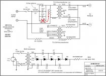
if the 16 ohms is connected one side to GND and the other to the capas, using the tap and connect it to the trafo red wire is like having a resistor is serial and one to GND. is like the drawing i attaché.
Cheers,
Williams,
Correct. And with R1= 1ohm and R2=15ohm you match the parts values that you have in your interface boxes now.
Also, notice that since they are in series, it does not matter if R1 comes before or after the capacitors.
I left it before the capacitors in my earlier post(#16) since that is the way your interfaces were already wired.
Changing the 15 ohm resistor connection was all that was required to achieve the Acoustat "C" version.
It may not by 100% the same physical layout as AcoustatAnswerMan mentioned, but it is electrically 100% the same, and that is what matters.
I hope I didn't confuse matters by trying to minimize the number of parts you had to move in your interfaces.
Last edited:
Dear all,
Last winter I tried many configuration on my 1+1 and here are what I got :
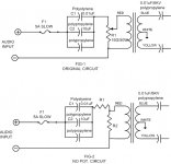
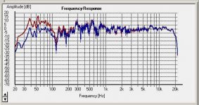
- Filtering the 1+1 at 75Hz with a 6db or 12db/oct passive filter between the preamp and the amp gives tremendous improvement at high levels (symphonic orchestra, rock...). See the pics (red original-blue with filter) herejoined - with and without filtering. But this works only with a good sub, good filter, good amp...
- I got some improvement by adding a step to the high tension ladder (mainly dynamics). But this increase in dynamics gives the feeling that the speakers have less bass-medium.
- I got better stereo by re-building the complete high tension ladder with new caps and diodes (see the 'high sound level limits' thread).
- More interesting, I got a big improvement by changing the yellow original caps (polyester ?) against MKP (polypropylene caps). But Bear advised me, that the MKP I used were not enough high-tension and that I should go back to the original caps. I did it -for my Acoustat sake- , through the nice supply of M.James.
But...
It sounds less good. Why ? no idea. Basically, the voices are more harsh, and the stereo less wide. We are talking about very good speakers, so the difference is not so big.
But there is a difference, and as 1+1 weak point is the directivity, I was quite happy with the MKP caps.
So I'm looking for high tension MKP,s...
These speakers are incredible, indeed,
Mathieu
Last winter I tried many configuration on my 1+1 and here are what I got :
- Filtering the 1+1 at 75Hz with a 6db or 12db/oct passive filter between the preamp and the amp gives tremendous improvement at high levels (symphonic orchestra, rock...). See the pics (red original-blue with filter) herejoined - with and without filtering. But this works only with a good sub, good filter, good amp...
- I got some improvement by adding a step to the high tension ladder (mainly dynamics). But this increase in dynamics gives the feeling that the speakers have less bass-medium.
- I got better stereo by re-building the complete high tension ladder with new caps and diodes (see the 'high sound level limits' thread).
- More interesting, I got a big improvement by changing the yellow original caps (polyester ?) against MKP (polypropylene caps). But Bear advised me, that the MKP I used were not enough high-tension and that I should go back to the original caps. I did it -for my Acoustat sake- , through the nice supply of M.James.
But...
It sounds less good. Why ? no idea. Basically, the voices are more harsh, and the stereo less wide. We are talking about very good speakers, so the difference is not so big.
But there is a difference, and as 1+1 weak point is the directivity, I was quite happy with the MKP caps.
So I'm looking for high tension MKP,s...
These speakers are incredible, indeed,
Mathieu
Attachments
Last edited:
- Status
- Not open for further replies.
- Home
- Loudspeakers
- Planars & Exotics
- Acoustat 3- MK121C