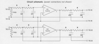
I’m implementing an active crossover section of the amplifier. The circuit is shown on attached. The calculated value of the resistors used in the circuit is 7.70 kOhms. However, I already have 7.32 kOhms resistors in my hand. In passive crossover, the difference between 7.70 and 7.32 kOhms is relatively large. But, in active crossover, could it be accepted for this difference? I’d like to ask for opinions should I buy the 7.70 kOhms or use the compromising 7.32 kOhms?
Attachments
Thats a 5% error, that means the corner frequency would also be 5% higher. You have to decide if you can deal with that. Of more concern are the capacitor values and tolerances. Errors in them will affect both the Q and the corner. As 1% resistors are cheap today, I would just get what you need. 1% capacitors are another thing.
Were this my circuit and I cared about 5% or more errors, I would accurately measure the target capacitors values and tweak the resistors values till the correct response was achieved in SPICE simulation, or if you want to, a bit of algebra can also get you there. Then I would order 1% resistors that are optimized for those capacitors. Keep in mind that the 4 resistors for each biquad will no longer have equal values as assumed in the schematic.
Another approach is to order a scad of capacitors, and hope there is enough spread to find the values you want. Or, just spend the money for precise capacitors.
Yea a big pain but will achieve nearly ideal filter responses.
More important is the matching of the all-equal resistors.
If you are only using 5% capacitors, this is not so important.
Remember that the time constants are the product of R and C.
For accuracy both must be held equally precise.
If you are only using 5% capacitors, this is not so important.
Remember that the time constants are the product of R and C.
For accuracy both must be held equally precise.

Although I can't claim expertise in electronics, your explanation resonates with me quite well.Thats a 5% error, that means the corner frequency would also be 5% higher. You have to decide if you can deal with that. Of more concern are the capacitor values and tolerances. Errors in them will affect both the Q and the corner. As 1% resistors are cheap today, I would just get what you need. 1% capacitors are another thing.
Were this my circuit and I cared about 5% or more errors, I would accurately measure the target capacitors values and tweak the resistors values till the correct response was achieved in SPICE simulation, or if you want to, a bit of algebra can also get you there. Then I would order 1% resistors that are optimized for those capacitors. Keep in mind that the 4 resistors for each biquad will no longer have equal values as assumed in the schematic.
Another approach is to order a scad of capacitors, and hope there is enough spread to find the values you want. Or, just spend the money for precise capacitors.
Yea a big pain but will achieve nearly ideal filter responses.
In my own experience, I've rarely encountered through-hole capacitors with tolerances below 5%. However, I have come across capacitors boasting an impressive 1% tolerance in the 1206 and 1210 packages. If you possess the skill to solder these components, you could potentially achieve an exceptionally precise match for frequency response or signal splitting.
After having simulation again by software, luckily, the 7.32kOhms seems to give more proper result.
Thank you for all advices.
Thank you for all advices.
You need to start with the capacitors since they do not come with the precision that resistors do. Once you have measured the capacitors and determined the ideal resistors, a more precise value can be achieved with two resistors, for example 820 in parallel with 12k, or 680 in series with 91. However, bear in mind that an arbitrary frequency like 1KHz is not likely more "correct" than what you get from more convenient component values.
PS. a spread sheet table of value combinations is a useful way to pick values.
PS. a spread sheet table of value combinations is a useful way to pick values.
Last edited:
Keep in mind the possibility of who cares, just throw it down with whatever you have, listen, and call it good enough.
- Home
- Amplifiers
- Solid State
- Acceptable range on the deviation of the resistor