Hello
What are the pros and the con of rush cascode input amp vs ltp input amp ?
Thank
Bye
Gaetan
What are the pros and the con of rush cascode input amp vs ltp input amp ?
Thank
Bye
Gaetan
Some simulation and measurement results here - Mr Evil's Realm - Rush Cascode Input Stage
Last edited:
Member
Joined 2009
Paid Member
The LTP provides zero dc-offset, a significant advantage. It doesn’t have a broad operating range and so for best linearity when used as the error amplifier in a global feedback amp you may do better with high feedback factors. The Rush is no more linear than the LTP as far as I can see.
Last edited:
What are the pros and the con of rush cascode input amp vs ltp input amp ?
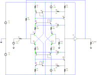
The first and the most advantage is that the rush cascode have no parasitic channel via base-collector (gate-drain) capacitance in the second stage.

Just because of this rush cascode have better HF-stability and predictive operation in dozens of MHz freq. range.
Also it have better isolation from supply ripple.
There are many opamps based on this topology, at least well known AD797 and THS4011/4021.


The first and the most advantage is that the rush cascode have no parasitic channel via base-collector (gate-drain) capacitance in the second stage.
View attachment 642922
Just because of this rush cascode have better HF-stability and predictive operation in dozens of MHz freq. range.
Also it have better isolation from supply ripple.
There are many opamps based on this topology, at least well known AD797 and THS4011/4021.
View attachment 642923
View attachment 642924
I can only see a folded cascode example in your schematics, but no rush cascode, A rush cascode is formed when both emitters from separate transistors meet each other.🙂
A rush cascade has two opposite gender devices connecting their emitters/sources and passing just one current. This variant is not the same as a conventional cascode. Effectively, you have an input emitter follower driving the emitter of a common base, with its base referenced to maintain 1.3V between the two bases. This configuration is extremely fast because the parasitics are greatly reduced, mostly because the common base configuration is very, very low impedance drive and base is at virtual ground.
Kanwar is right on the money......
HD
Kanwar is right on the money......
HD
Last edited:

interesting thread. some additional URL's:
Mr Evil's Realm - Rush Cascode Input Stage
The Rush Cascode: Possible Wiki page (#8)
4QD-TEC: Low distortion Audio amplifier
Input stage idea (#25+26)
Mr Evil's Realm - Rush Cascode Input Stage
Input stage idea
(#25)
The sound of cascodes (#66)
Mr Evil's Realm - Rush Cascode Input Stage
The Rush Cascode: Possible Wiki page (#8)
4QD-TEC: Low distortion Audio amplifier
Input stage idea (#25+26)
Mr Evil's Realm - Rush Cascode Input Stage
Input stage idea
(#25)
The sound of cascodes (#66)
Last edited:

The LM741 (UA741) op amp uses this style of cascoding on its input pair. It was designed by a guy named Dave Fullagar and released by Fairchild in 1968. I've never heard anyone call it "rush" cascoding.
Here's a simplified schematic:
https://www.electronicshub.org/wp-c...IC-741-Op-Amp-Tutorial-Internal-Schematic.jpg
Here's a simplified schematic:
https://www.electronicshub.org/wp-c...IC-741-Op-Amp-Tutorial-Internal-Schematic.jpg
Last edited:
I'm going to have a crack at the advantages and disadvantages of the "Rush" cascode.
Disadvantages:
Gm cut by a factor of 2
Higher offset
Higher noise
Higher distortion (you have an input crossover now, too)
Tougher to stabilize (variable gain input stage)
Advantages:
Extremely high slew rates are possible because the operating current is not limited by a fixed current source.
A standard differential input pair driving some kind of VAS has plenty of slew rate, so few designers have been willing to pay for higher slew rates with higher THD and noise.
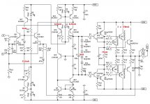
I've attached a picture of Mr. Evil's final schematic. It's basically a classic AB input amp with the Rush cascoding added. He actually does a good job of pointing out the pros and cons of the Rush cascode here:
Mr Evil's Realm - Rush Cascode Input Stage
Disadvantages:
Gm cut by a factor of 2
Higher offset
Higher noise
Higher distortion (you have an input crossover now, too)
Tougher to stabilize (variable gain input stage)
Advantages:
Extremely high slew rates are possible because the operating current is not limited by a fixed current source.
A standard differential input pair driving some kind of VAS has plenty of slew rate, so few designers have been willing to pay for higher slew rates with higher THD and noise.
I've attached a picture of Mr. Evil's final schematic. It's basically a classic AB input amp with the Rush cascoding added. He actually does a good job of pointing out the pros and cons of the Rush cascode here:
Mr Evil's Realm - Rush Cascode Input Stage
Attachments
Last edited:
And, I just got back from the "other" thread where forr pointed out the Rush circuit is NOT a cascode. It's another version of an emitter-coupled pair.
I hate the term "long-tailed pair," but if you're going to use it, it is appropriate to call the Rush circuit a "no-tailed pair. Recognize that these are both emitter-coupled pairs with the same small signal model.
I hate the term "long-tailed pair," but if you're going to use it, it is appropriate to call the Rush circuit a "no-tailed pair. Recognize that these are both emitter-coupled pairs with the same small signal model.
I'm going to have a crack at the advantages and disadvantages of the "Rush" cascode.
Disadvantages:
Gm cut by a factor of 2
Higher offset
Higher noise
Higher distortion (you have an input crossover now, too)
Tougher to stabilize (variable gain input stage)
Advantages:
Extremely high slew rates are possible because the operating current is not limited by a fixed current source.
I assume these are a comparison to an LTP. Therefore:
Given the same total quiescent current, the NTP (I am happy at least one other person called it that, even if reluctantly 🙂) has DOUBLE the Gm, because the bias current is not split between the transistors as in the LTP. So Gm is doubled because Ic is doubled. So maybe it is fair to add 54mV of degeneration to bring the Gm back to the same level, which increases BW and helps with the variable gain problem (limits it to a maximum rise of 2x).
However, if instead we keep collector current per transistor the same, the Gm comes out equal. and the quiescent current of the LTP ends up twice the current of the NTP.
Which of these scenarios is more valid depends on your reasons for comparing the LTP with the NTP.
Of course if you add NPN/PNP buffers to eliminate the offset of the NTP, then if all transistors have the same quiescent you lose the advantage of double Gm, but gain the advantage of low offset (though still not quite as low as the LTP).
Of course the NTP will always have more inherent distortion. But, that only matters if your input stage is the dominant source of distortion which in most modern amps, just isn't the case.
Noise:
Comparing it with the LTP at the same total quiescent, the NTP has less noise because both transistors have double the Ic.
So I would say both Gm and noise are advantages, or at least equal, and shouldn't be considered disadvantages.
On the other hand PSRR and CMRR are both disadvantages you didn't mention.
Last edited:
I see what you're getting at Keantoken. I caused confusion by being ambiguous. I was looking at 4 different circuits with complementary E-C devices: The LM741, which uses a pair of E-C pairs (2 NPN and 2 PNP) with a long-tail current source in between them. So that configuration has a gm/4 limitation.
In short, I agree with almost everything you say. Especially true is that the complementary E-C connection has 1/2 the total current of the matched diff pair. I also agree with you about the noise being 3-dB lower in the complementary E-C pair, because they have the same current, and not two uncorrelated currents. So I retract my statement there.
I didn't mention PSRR and CMRR, because I think those are more a factor of circuits external to the E-C pair. The inherent balance of the E-C diff pair surely helps with both, so I think in general, you're right, all else being equal.
It's fruitful to redo the comparison multiple times, allowing a higher transistor count each time. For instance if we limit to only 2 transistors, the LTP gets a poor CCS, whereas the NTP gets poor offset. If we limit to 4 transistors, the LTP gets either a good CCS, input buffers, a current mirror, or a cross-quad, whereas the NTP gets either a current mirror or poor input buffers (fed by resistors).
Of course even at 4 transistors are many more options for both differentials, almost too many to list. Allow 6 transistors and the scope of possible configurations becomes so huge one may reach the limit of their knowledge in being able to contend with all possible advantages or disadvantages. And one could repeat the same analysis for each VAS and output stage, and combination thereof. What do you want to bet that someone who publishes a 50-transistor amplifier has not used each transistor to nearly it's full potential?
Of course even at 4 transistors are many more options for both differentials, almost too many to list. Allow 6 transistors and the scope of possible configurations becomes so huge one may reach the limit of their knowledge in being able to contend with all possible advantages or disadvantages. And one could repeat the same analysis for each VAS and output stage, and combination thereof. What do you want to bet that someone who publishes a 50-transistor amplifier has not used each transistor to nearly it's full potential?
Last edited:
- Home
- Amplifiers
- Solid State
- About rush cascode input amp vs ltp input amp