I was playing with my Mofo with mosfets initially and all went fine with A2CMx. About A2CMx you can find out more here
Things changed when I wanted to add SITs to the Mofo. I needed to add an extra resistor in series with the inductor to create the needed negative voltage to bias the SIT, then depending on SIT vgs the value of this resistor could be different for each channel if the vgs is not tightly matched so very difficult adjustability of bias current.
To mention that this resistor degrades the performance of the amp specially at 4r. There is a good thing about the resistor solution... it is cheap and with a bit of patience it gets you to Rome the cheapest way.
Hmm but this was not what I wanted.. I was looking for the best performance I could get and also bias adjustability.
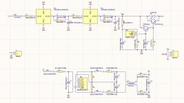
So I added to the A2CMx a dcdc converter that gets the positive voltage from the input of A2CMx and makes it negative. The dcdc has dual stage rlc filtering. This way you get a clean output voltage of close to -30V from an input voltage of positive 12V(some dcdc models start higher or lower) to 36V.
Depending on the dcdc converter that you will fit on the pcb(1-3w) you can get up to 100ma. To drive the SIT gate in a Mofo a 1W dcdc is enough.
You will need to add a 100K trimmer across the negative output and tap the relatively small(-2v -3v) negative gate voltage for the sit. You will measure this voltage with the + probe of the dmm on the gnd of A2CMx-V and the - probe on the cursor of the trimmer. From this same trimmer you will adjust the bias from now on when you use SITS with you Mofo.
Then another use for it can be to power an OS like Mofo with SIT and also a front end that requires bipolar voltage to work. I am using it like this in my Gaincore project where I get very good performance and sound with this I mean that the design has some time since is being tested and it works as expected.
Now to make this stuff even more interesting I can tell you that you can use also a lithium battery for this stuff which in this case without the negative rail generator would have required another battery. ONE IMPORTANT THING: WHEN USING LIYHIUM BATTERIES ADD A BMS!!!
The maximum voltage that A2CMx-V accepts at it`s input is limited to 32V because of the dcdc converter which has a maximum input voltage of 36V.
On the positive high current output you can get up to 3A with the listed components but even higher currents are possible if the inductors are replaced. Tried bigger inductors(because the listed ones were out of stock) but went up to only 3.5A and it worked fine until here.
At this time this is what comes through my mind to write. If there will be else I will be back.
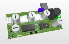
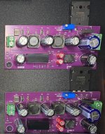
Until then I am sharing the schematic, bom and gerbers so everybody with a SIT Mofo(and not only..) can build this module and explore it`s amp at greater performance and sound!

Later edit:
If you find there are bom components out of stock you can ask here and I will try to help in finding replacements.
Things changed when I wanted to add SITs to the Mofo. I needed to add an extra resistor in series with the inductor to create the needed negative voltage to bias the SIT, then depending on SIT vgs the value of this resistor could be different for each channel if the vgs is not tightly matched so very difficult adjustability of bias current.
To mention that this resistor degrades the performance of the amp specially at 4r. There is a good thing about the resistor solution... it is cheap and with a bit of patience it gets you to Rome the cheapest way.
Hmm but this was not what I wanted.. I was looking for the best performance I could get and also bias adjustability.
So I added to the A2CMx a dcdc converter that gets the positive voltage from the input of A2CMx and makes it negative. The dcdc has dual stage rlc filtering. This way you get a clean output voltage of close to -30V from an input voltage of positive 12V(some dcdc models start higher or lower) to 36V.
Depending on the dcdc converter that you will fit on the pcb(1-3w) you can get up to 100ma. To drive the SIT gate in a Mofo a 1W dcdc is enough.
You will need to add a 100K trimmer across the negative output and tap the relatively small(-2v -3v) negative gate voltage for the sit. You will measure this voltage with the + probe of the dmm on the gnd of A2CMx-V and the - probe on the cursor of the trimmer. From this same trimmer you will adjust the bias from now on when you use SITS with you Mofo.
Then another use for it can be to power an OS like Mofo with SIT and also a front end that requires bipolar voltage to work. I am using it like this in my Gaincore project where I get very good performance and sound with this I mean that the design has some time since is being tested and it works as expected.
Now to make this stuff even more interesting I can tell you that you can use also a lithium battery for this stuff which in this case without the negative rail generator would have required another battery. ONE IMPORTANT THING: WHEN USING LIYHIUM BATTERIES ADD A BMS!!!
The maximum voltage that A2CMx-V accepts at it`s input is limited to 32V because of the dcdc converter which has a maximum input voltage of 36V.
On the positive high current output you can get up to 3A with the listed components but even higher currents are possible if the inductors are replaced. Tried bigger inductors(because the listed ones were out of stock) but went up to only 3.5A and it worked fine until here.
At this time this is what comes through my mind to write. If there will be else I will be back.
Until then I am sharing the schematic, bom and gerbers so everybody with a SIT Mofo(and not only..) can build this module and explore it`s amp at greater performance and sound!
Later edit:
If you find there are bom components out of stock you can ask here and I will try to help in finding replacements.
Attachments
Last edited:
