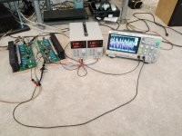
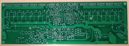
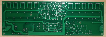
Here I introduce the HHCA (Homage HCA) amplifier design. About a year ago I built an amplifier I "designed"... or more like copy-pasted and sprinkled some luck on 😀
It's a mix of the Yamaha MX-1 input stage, the discrete HCA amplifier from something earlier, and a more standard output stage (no Class G).
Wanted an 80's/90's Yamaha amplifier for a while but they are a bit pricey, so decided to roll my own.
PCB layout was designed with flexibility in mind.
I have tested this up to +/-31V as that is all my bench supply gives, but it has had a good thrashing on and off for the past year. It worked first time, even with a missing solder joint so not all of my output transistors were working, I didn't notice for a few months.... 🙄
If you power up all equipment at the same time, with a current limit on the supply to this design, with a large switch on thump present on the input, it will latch up until you power cycle. Either phase the power up of your equipment, or have a good few of these - remove the current limit, and pray to god it's ok.... Honestly I have had this happen twice by accident with my current limit set at 1A or so, but not with current set higher than this.
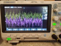
I have not made proper audio measurements, but I think it sounds pretty awesome, seems dead quite with my ear up to my tweeters, and doesn't do anything horrible if you mess around with the inputs when they are disconnected or feed it square waves.


View attachment HHCA 1.1 Schematic.pdf
View attachment HHCA 1.1 PCB Front Layout.pdf
View attachment HCA 1.1 PCB Gerbers.zip
View attachment HCA 1.1 PCB Layers in PDF.zip
View attachment HHCA 1.1 Bill of Materials.zip
Warnings:
I have no interest if the Hyperbolic Conversion Amplifier (or hyper b******* amplifier if you prefer) actually works, but I think this sounds pretty good. Maybe if you remove the HCA part and hook the output stage to the input stage it might sound the same (maybe I should try that sometime).
This design should (theoretically) be good upto +/-75V if you replace the medium power transistors with KSA1381 and KSC3503 parts, and if any resistors start smoking just put bigger parts in 😉 - However these transistors have lower output capacitance and may impact stability!
Edit:
Knew I would forget something. Supply voltage with specified parts is +/-30V to +/- 50V. PCB is 2 layer, recommend 2oz copper if you want to push it a bit. Gain should be around 28dB. Input sensitivity...feed her till she pops!
It's a mix of the Yamaha MX-1 input stage, the discrete HCA amplifier from something earlier, and a more standard output stage (no Class G).
Wanted an 80's/90's Yamaha amplifier for a while but they are a bit pricey, so decided to roll my own.
PCB layout was designed with flexibility in mind.
I have tested this up to +/-31V as that is all my bench supply gives, but it has had a good thrashing on and off for the past year. It worked first time, even with a missing solder joint so not all of my output transistors were working, I didn't notice for a few months.... 🙄
If you power up all equipment at the same time, with a current limit on the supply to this design, with a large switch on thump present on the input, it will latch up until you power cycle. Either phase the power up of your equipment, or have a good few of these
 - remove the current limit, and pray to god it's ok.... Honestly I have had this happen twice by accident with my current limit set at 1A or so, but not with current set higher than this.
I have not made proper audio measurements, but I think it sounds pretty awesome, seems dead quite with my ear up to my tweeters, and doesn't do anything horrible if you mess around with the inputs when they are disconnected or feed it square waves.


View attachment HHCA 1.1 Schematic.pdf
View attachment HHCA 1.1 PCB Front Layout.pdf
View attachment HCA 1.1 PCB Gerbers.zip
View attachment HCA 1.1 PCB Layers in PDF.zip
View attachment HHCA 1.1 Bill of Materials.zip
Warnings:
I have no interest if the Hyperbolic Conversion Amplifier (or hyper b******* amplifier if you prefer) actually works, but I think this sounds pretty good. Maybe if you remove the HCA part and hook the output stage to the input stage it might sound the same (maybe I should try that sometime).
This design should (theoretically) be good upto +/-75V if you replace the medium power transistors with KSA1381 and KSC3503 parts, and if any resistors start smoking just put bigger parts in 😉 - However these transistors have lower output capacitance and may impact stability!
Edit:
Knew I would forget something. Supply voltage with specified parts is +/-30V to +/- 50V. PCB is 2 layer, recommend 2oz copper if you want to push it a bit. Gain should be around 28dB. Input sensitivity...feed her till she pops!

Last edited:
Last edited:
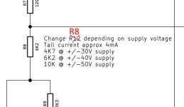
What about the 30/40/50V values for R20/R21 and R8 mentioned in the BOM? They are not in the schematic.
A more detailled BOM...
Nice one Algar_emi - if you can buy/import from lcsc.com (where I get a lot of parts these days) you can get like 100 KTA1268 for around $2! Really useful for matching the current mirror pairs.
Even their passive parts are much cheaper than the normal suppliers. Mostly Chinese suppliers but not had anything that is questionable quality yet. Not bought any off brand electrolytic capacitors though...
How stable is the bias over temperature? There is no compensation when I'm seeing it right...
TR11 and TR12 track temperature for bias as part of the HCA circuit. VR1 is used to asjust the bias from nothing to, I can't remember how high. 😕
They seems pretty stable. I am only running around 40mA bias per transistor, so 320mA across 2 amps. Idle current drops a little (~300mA) when you've warmed them up.
I've had my test rig uncomfortably hot to touch on the heatsinks. Think I measured 50C+ on the heatsinks at one point, the amp didn't mind, bias was stable but decreasing (no runaway).
Last edited:
Thanks for the tip with this supplier. Will look at it.
At what voltage did you run your prototype, I can see 2 pairs per heatsink?
SB
At what voltage did you run your prototype, I can see 2 pairs per heatsink?
SB
+/-31V is all my bench PSU will give me 🙁
I used some old original 2CS5200/2SA1943 parts removed from an abused amp for testing. As some of my speaker drop to 3 ohms I put an extra pair in to be safe Not really needed at that supply voltage but planning for when I can push it higher so I don't have to dismount it off the heatsinks.
Looking at getting a better PSU. Maybe another bench supply to link in series, if they will power up like that, to get at lest +/-60V.
The design has been simulated mainly for power calculations (SiMetrix Elements) upto +/-70V or +/-75V, I can't remember exactly, but it was over spec'd. Should be margin in the design even up at those supply voltages, although will need high voltage medium power transistors.
As it is a close copy of the Yamaha designs, and as they changed so much each version (some having FET input and others not, some discrete HCA circuits and some with the IC), I assumed the basic topology is pretty stable
I used some old original 2CS5200/2SA1943 parts removed from an abused amp for testing. As some of my speaker drop to 3 ohms I put an extra pair in to be safe
 Not really needed at that supply voltage but planning for when I can push it higher so I don't have to dismount it off the heatsinks.
Looking at getting a better PSU. Maybe another bench supply to link in series, if they will power up like that, to get at lest +/-60V.
The design has been simulated mainly for power calculations (SiMetrix Elements) upto +/-70V or +/-75V, I can't remember exactly, but it was over spec'd. Should be margin in the design even up at those supply voltages, although will need high voltage medium power transistors.
As it is a close copy of the Yamaha designs, and as they changed so much each version (some having FET input and others not, some discrete HCA circuits and some with the IC), I assumed the basic topology is pretty stable

- Home
- Amplifiers
- Solid State
- A Yamaha Hyperbolic Conversion (HCA) Clone - The HHCA
