It's been a little while since I finished my last amplifier, so I feel the need to build a new one. My last amp, the choke loaded LU1014D cascode follower was inspired by Nelson Pass's Zen Variations #9 article, and since I still have a bunch of LU1014Ds laying around, I figured, why not do another variation. I have only one common source amplifier, the BAF 2015 THF-51S, and it's feeling lonely among all my source follower amps, so I decided to do a choke loaded variation of the Zen Variations #9. I've got to admit, I was also influenced by the Zenductor.
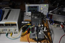
I did some simulations on LTspice and then put together a prototype using parts that I had in-house. I wanted to test the design before committing to building a finished product. I used a lab power supply and recycled my previous LU1014D follower prototype. For the choke, I happened to have an unused Hammond 193U.
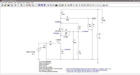
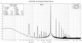
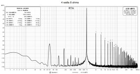
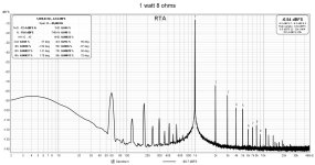
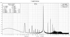
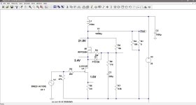
I adjusted the cascode to produce a dominant second order harmonic with decreasing higher order harmonics. With a power supply of 22V, the choke drops 3.4V, MOSFET Vds of 11.1V, JFET Vds of 6.0V, and 1.44V at the 0.7 ohm source resistor, which results in a current of around 2 amps. The amplifier gain is about 9 times.
The THD at 1 watt into 8 ohms is about 0.22% and at about 1.1%, the output is 9.2 watts.
I haven't played any music through it yet, but I will use it to drive one Quad ESL and use my source follower L1014D amp to drive the other ESL. It will be interesting to see how the two topologies compare.
I just received a bunch of aluminum PCBs for my unmounted SMD LD1014Ds and my next task is to get them soldered up and matched with my super-duper FrankenTracer. Then I can test the prototype amp with a variety of JFETs and operating points.
.
I did some simulations on LTspice and then put together a prototype using parts that I had in-house. I wanted to test the design before committing to building a finished product. I used a lab power supply and recycled my previous LU1014D follower prototype. For the choke, I happened to have an unused Hammond 193U.
I adjusted the cascode to produce a dominant second order harmonic with decreasing higher order harmonics. With a power supply of 22V, the choke drops 3.4V, MOSFET Vds of 11.1V, JFET Vds of 6.0V, and 1.44V at the 0.7 ohm source resistor, which results in a current of around 2 amps. The amplifier gain is about 9 times.
The THD at 1 watt into 8 ohms is about 0.22% and at about 1.1%, the output is 9.2 watts.
I haven't played any music through it yet, but I will use it to drive one Quad ESL and use my source follower L1014D amp to drive the other ESL. It will be interesting to see how the two topologies compare.
I just received a bunch of aluminum PCBs for my unmounted SMD LD1014Ds and my next task is to get them soldered up and matched with my super-duper FrankenTracer. Then I can test the prototype amp with a variety of JFETs and operating points.
.
Attachments


With that beefy choke and cascode device, you could run your PSU up to 36V for more power into demanding speakers.
That is a beefy choke. It's rated at 200mH at 2A with DC resistance of 1.7 ohms. My intention is to use the Hammond 159ZC instead, but I don't have one on hand so I used the 193U for the prototype.
The 159ZC has less inductance, 60mH at 2A, but it is sufficient. On the plus side, it is smaller (less weight) and its DC resistance is lower (0.7 ohms). At 1 ohm less resistance than the 193U, there will be a gain of 1.5 to 2 volts of available voltage.
As for driving the Quad ESLs, I have other SIT amps that have higher power output. The ESLs are meant to be used with a low heat producing amp for summer time listening (instead of my bi-amped JBLs). My Lovoltech source follower was built for that purpose. It worked quite well. Actually, it's still in the system and I'm enjoying it so much that I haven't changed over to my JBLs yet.
A minor issue with the present LD1014D follower amp is that I didn't build it with a voltage gain stage front end, so there is the odd CD that can't drive the ESLs to the output level that I would like. So, if this new common source amp sounds good with the ESLs, the problem is solved.
A nice looking amp, congratulations!
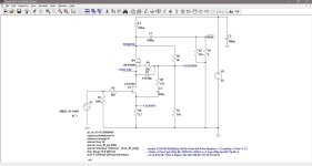
Would you mind explaining why bias resistor R6 is connected to M1 drain and not to the +22V power supply? In either case, (R6, R7, and C3) filter out and remove all traces of signal, leaving only a DC voltage for biasing. But isn't the +22V power supply more stable / predictable / dependable, than the drain voltage? Thanks for any insight!!
Would you mind explaining why bias resistor R6 is connected to M1 drain and not to the +22V power supply? In either case, (R6, R7, and C3) filter out and remove all traces of signal, leaving only a DC voltage for biasing. But isn't the +22V power supply more stable / predictable / dependable, than the drain voltage? Thanks for any insight!!
you could use a second choke instead of the 0.7r resistor to dinuish a bit the gain and linearize a bit?
maybe a single core with 2 windings one for source and one for drain?
maybe a single core with 2 windings one for source and one for drain?
A nice looking amp, congratulations!
Would you mind explaining why bias resistor R6 is connected to M1 drain and not to the +22V power supply? In either case, (R6, R7, and C3) filter out and remove all traces of signal, leaving only a DC voltage for biasing. But isn't the +22V power supply more stable / predictable / dependable, than the drain voltage? Thanks for any insight!!
I was following the schematic from Zen Variations #9. However, what you say is true about no AC present at the gate. Nelson does talk about cascode modulation.
I will try some changes to introduce some of the AC to the MOSFET gate.
For me, the cost in terms of weight and space would not lead me to substitute a choke for the resistor. Also, the resistor value can be easily changed to adjust the bias.
After that great question from Mark, I got on LTspice and looked at the AC signals at various points of the cascode and came up with the scheme shown on the new schematic.
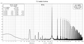
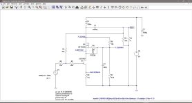
The new arrangement feeds AC to the MOSFET gate and R9 is a variable resistor which I use to set the magnitude of that signal. I set R9 for minimum harmonic distortion at the output. For this prototype amp, it is 170 ohms.
In general, the distortion has decreased at all levels of power output except at the very high end, although accepting higher distortion at low output would have increased the maximum power output at a given distortion level. The THD at 1 watt out into 8 ohms is now 0.044%. The 1% THD power is 7.2watts.
Attachments

If you look at the Zen 9 Nelson only has about 2V drain to source and I assume
that when the amp clips there may be about 4V drain to source across the Ld1014D.
Well I assumed having a few more volts drain to source like you do in your design
might be a good idea. But one of our members showed some curves he ran on his
Ld1014D and they looked normal till he got to almost exactly 6V drain to source and
then the device started acting horrible. Sorry I don't recall what thread and post that
was in.
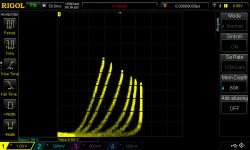
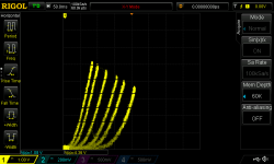
The LD1014D's characteristics vary greatly, so low distortion operating points will vary as well. I have traced a number of devices and have seen the variations. These two curves were created under the same conditions and you can see they are quite different.
In my amps, I vary the source resistance (if possible) and the bias of the cascode MOSFET while measuring distortion at output to achieve the distortion spectrum that I want. It happens that in this case, Vds of 6V works for me.
In my amps, I vary the source resistance (if possible) and the bias of the cascode MOSFET while measuring distortion at output to achieve the distortion spectrum that I want. It happens that in this case, Vds of 6V works for me.
Attachments
Following up on the subject of acceptable Vds for the LD1014D, I looked back at the measurements that I have on my cascoded LD1014D source follower amp. The LD1014D that I used on that prototype amp is the same one that I am using for this new amp prototype.
The operating point of the LD1014D in the source follower prototype ended up at Vds = 5.54V and Iq = 1.65A. The very same LD1014D in this new prototype is operating at 6.0V and 2.0A. So, the two operating points are similar.
For the final version of the LD1014D source follower amp, I used a matched pair that had some nice looking curves and their final operating points ended up at 3.44Vds, 2.0A and 3.24Vds, 2.0A.
I have not curve traced the LD1014D used in the prototypes, but I think I will, just to see how "ugly" its curves look.
I spent the last few days going backwards and forwards on this amp.
I was feeling good about the prototype after getting the THD down to good levels, so I decided to do a frequency response measurement. I had been doing some other testing, so everything was powered up. When I disconnected my 1 kHz oscillator from the amp's input, instantly, my lab power supply went into current limiting mode. Not a good sign. It was the dreaded LU1014D gate leakage issue.
Apparently, Victor's low distortion oscillator has low enough output impedance that the leakage current was not a problem. Hoping this particular LD1014D had an uncharacteristically high gate leakage, I replaced it with a different LD1014D. This new LD1014D is one that I had curve traced and it has some nice triode-like curves. Alas, it was Groundhog Day. Same result.
So, I had to backtrack. I suppose I could add a buffer at the front end. Or lower the LU1014D's Vds. The easy thing to do is to lower the Vds, so that's what I ended up doing. I found that somewhere between 3V and 3.5V of Vds, measurable gate current was observed. I ended up settling on Vds of 2.4V and with a source resistor of 0.6 ohms, that gave a current of 1.5A. I had tried a variety of source resistances and found that 0.6 ohms produced the lowest distortion.
At lower Vds, distortion levels were higher and the 3rd harmonic was almost up to the level of the 2nd harmonic. I could reduce the total distortion with fine Vds adjustments, but then the 3rd harmonic dominated.
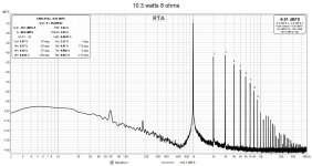
I found that my previous method of feeding AC from the JFET source to the MOSFET gate no longer effective for reducing distortion, but instead discovered that taking the signal from the MOSFET drain worked. Again, I used a variable resistor to control the signal magnitude and managed to lower the total distortion to 0.09% at 1 watt, although with 3rd harmonic dominant.
However, output power increased somewhat to 10.3 watts into 8 ohms at 3% THD.
I think the dominating 3rd harmonic distortion at lower Vds may be a characteristic of this particular LD1014D. I'll have to try different devices at some point to check this out.
With regard to 3rd harmonic distortion, I need to give it a listen to see what I think. Nelson P has done some research into 2nd or 3rd harmonic preferences and it appears that some people like 3rd. But then, this amp has both, so who knows? The good thing is that the 5th and 7th harmonics are quite low.
I haven't played any music with this amp yet, so that's the next step. After that, I see some feedback on the horizon.
I was feeling good about the prototype after getting the THD down to good levels, so I decided to do a frequency response measurement. I had been doing some other testing, so everything was powered up. When I disconnected my 1 kHz oscillator from the amp's input, instantly, my lab power supply went into current limiting mode. Not a good sign. It was the dreaded LU1014D gate leakage issue.
Apparently, Victor's low distortion oscillator has low enough output impedance that the leakage current was not a problem. Hoping this particular LD1014D had an uncharacteristically high gate leakage, I replaced it with a different LD1014D. This new LD1014D is one that I had curve traced and it has some nice triode-like curves. Alas, it was Groundhog Day. Same result.
So, I had to backtrack. I suppose I could add a buffer at the front end. Or lower the LU1014D's Vds. The easy thing to do is to lower the Vds, so that's what I ended up doing. I found that somewhere between 3V and 3.5V of Vds, measurable gate current was observed. I ended up settling on Vds of 2.4V and with a source resistor of 0.6 ohms, that gave a current of 1.5A. I had tried a variety of source resistances and found that 0.6 ohms produced the lowest distortion.
At lower Vds, distortion levels were higher and the 3rd harmonic was almost up to the level of the 2nd harmonic. I could reduce the total distortion with fine Vds adjustments, but then the 3rd harmonic dominated.
I found that my previous method of feeding AC from the JFET source to the MOSFET gate no longer effective for reducing distortion, but instead discovered that taking the signal from the MOSFET drain worked. Again, I used a variable resistor to control the signal magnitude and managed to lower the total distortion to 0.09% at 1 watt, although with 3rd harmonic dominant.
However, output power increased somewhat to 10.3 watts into 8 ohms at 3% THD.
I think the dominating 3rd harmonic distortion at lower Vds may be a characteristic of this particular LD1014D. I'll have to try different devices at some point to check this out.
With regard to 3rd harmonic distortion, I need to give it a listen to see what I think. Nelson P has done some research into 2nd or 3rd harmonic preferences and it appears that some people like 3rd. But then, this amp has both, so who knows? The good thing is that the 5th and 7th harmonics are quite low.
I haven't played any music with this amp yet, so that's the next step. After that, I see some feedback on the horizon.
Attachments

I never got around to listening the amp, but instead proceeded to adding negative feedback. That was an adventure itself as I managed to break the amp. Luckily, no parts were damaged. Just wiring problems.
I ended up redoing a good part of the wiring since entropy had prevailed, and a real rats nest of wires had developed. Since, I was rewiring, I traded out the LD1014D for a different specimen. I wanted to see the effect of different LD1014Ds on measured performance. I did not include feedback in the rebuild since I wanted do some measurements first without feedback for comparison purposes.
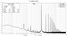
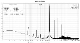
After I got everything going again, before adding feedback, I tried out different operating points in combination with different AC to the MOSFET gate. With this LD1014D, the best result was with the capacitor straight from the MOSFET gate to ground; effectively no AC signal. The lowest resulting THD was about 0.16% with 2nd harmonic dominant. The operating point of the LD1014D was 2.2Vds at 1.8A.
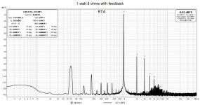
I was a bit disappointed, but that's life. It was getting dark, I was getting hungry, and I wanted to end the day on a happy note, so I decided to try adding feedback. The result was 0.044% THD at 1 watt, 8 ohms and the distortion spectrum looked decent. That made my day!
I ended up redoing a good part of the wiring since entropy had prevailed, and a real rats nest of wires had developed. Since, I was rewiring, I traded out the LD1014D for a different specimen. I wanted to see the effect of different LD1014Ds on measured performance. I did not include feedback in the rebuild since I wanted do some measurements first without feedback for comparison purposes.
After I got everything going again, before adding feedback, I tried out different operating points in combination with different AC to the MOSFET gate. With this LD1014D, the best result was with the capacitor straight from the MOSFET gate to ground; effectively no AC signal. The lowest resulting THD was about 0.16% with 2nd harmonic dominant. The operating point of the LD1014D was 2.2Vds at 1.8A.
I was a bit disappointed, but that's life. It was getting dark, I was getting hungry, and I wanted to end the day on a happy note, so I decided to try adding feedback. The result was 0.044% THD at 1 watt, 8 ohms and the distortion spectrum looked decent. That made my day!
Attachments
Great Job Bill
In addition, your Spice work seems to correlate rather well with your measurements.
This is not the case for me. Putting for instance schem 5 in Spice results in 2.15% THD in my simultation.
Is this a case of rotten LU1014 model i use, or another mistake from my side?

In addition, your Spice work seems to correlate rather well with your measurements.
This is not the case for me. Putting for instance schem 5 in Spice results in 2.15% THD in my simultation.
Is this a case of rotten LU1014 model i use, or another mistake from my side?
Hi Jost. I use my own model based on Frankentracer measured curves of one of my LD1014Ds. The LTspice model was produced by Michael Rothacher's SIT curve fitting app. I found that other models that I have tried do not work well at low Vds. I wrote about it in my LD1014D source follower amp posts.
The LTspice model that I use is attached.
Edit: used attachment for model instead of in text. Site does things to the text.
In my schem5 simulation, I get THD of 0.87%.
In real life, though, I have found that variations amongst the LD1014Ds that I have mean that the LTspice simulations only give a general picture of what to expect. The results can differ from device to device.
Attachments
Last edited:
- Home
- Amplifiers
- Pass Labs
- A Variation on Zen Variations #9 (Cascoded LU1014D) - Using Inductor Instead of CCS