You Can DIY! Meet the Pentriode
August 4 2022, 10:10Shortly after my first tube audio article, “The Mu Stage,” was published in 1993 in Glass Audio magazine, I developed a simple circuit that I called the Pentriode. I even wrote a tentative article about the Pentriode in 1995, and I considered submitting it around that time but somehow never got around to it. I finally decided now was the time for me to share a blast from my past as I show you the Pentriode, this time with additional information.
The Circuitry
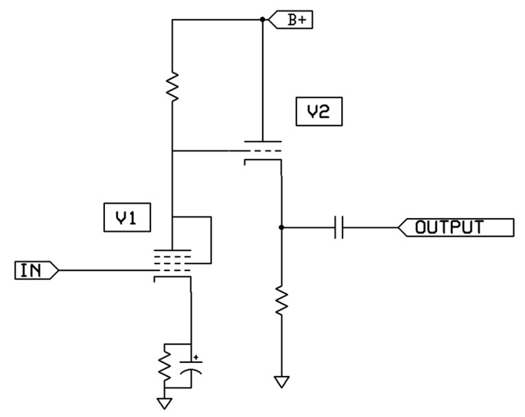
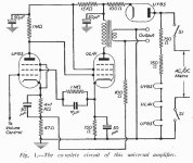
Probably everyone who reads anything about tube audio circuitry knows that a pentode can function as a triode when its screen grid (Grid 2) is connected to the plate — see V1 shown in Figure 1. When triode connected, many pentodes can be outstanding very linear triodes.
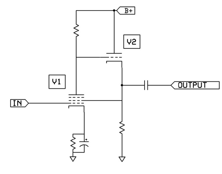
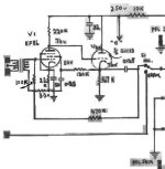
The Pentriode is formed by making one simple change to Figure 1: Connect V1’s screen grid, not to V1’s plate, but to the cathode of cathode follower (CF) V2—see Figure 2. In Pentriode mode, V1 essentially operates as a triode, but its screen grid current no longer burdens the plate of V1. Instead, CF V2 provides all current to V1’s screen grid. Pentriode mode brings nice advantages.
Pentriode mode is not strictly triode mode nor is it pentode mode. It is also not “ultra-linear” (aka partial-triode) operation. I had to come up with an entirely new name for this circuit, and the name Pentriode seemed appropriate. Pentriode mode is definitely most like a triode mode, with the same (or closely the same) mu and gain as the pentode would have in conventional triode connection. In fact, designing a Pentriode stage is as simple as designing a standard triode stage, the only extra part being the addition of a simple cathode follower.
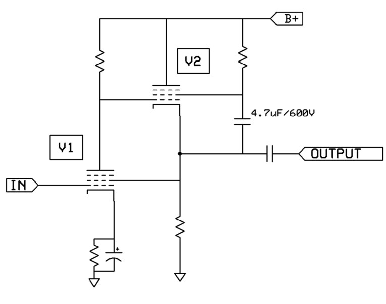
Cathode follower V2 can be any active device, including a triode CF or a pentode CF (my favorite follower for audio — see Figure 3). There are also several other options: You could make a hybrid Pentriode by using a field-effect transistor (FET) source follower in place of V2, or a bipolar junction transistor (BJT) emitter follower, or a Darlington emitter follower, or an insulated gate bipolar transistor (IGBT) emitter follower, or a Sziklai pair follower, or an IC voltage follower, or a current follower, and I’m sure several other follower types. V2 could also be a follower consisting of a vacuum-state device, solid-state device, gas-state device, or any state device.
By the way, it is my standard practice to use grid stopper resistors for every control grid and every screen grid. Suppressor grids don’t need a stopper resistor. In audio applications, I normally use a value of 220Ω for grid stopper resistors.
Pentriode’s Benefits
It is important to note that some pentodes really excel in Pentriode mode, more so than other pentodes. Some pentodes give even less distortion in Pentriode mode than when the pentode is connected in standard triode connection. It would be nice if we could tabulate a list of the pentodes that excel at Pentriode operation.
It is also possible to make a Pentriode mu stage, which is probably my favorite type of mu stage. It has all the advantages of mu stage operation including wide bandwidth (BW), low distortion, low output impedance, plus the advantages of Pentriode operation. A practical example is shown in Figure 4. With regard to Figure 4: 1) The purpose of the 27kΩ resistor is to drop a few DC volts so that V1’s screen grid voltage is the same as V1’s plate voltage, to closely emulate triode operating conditions for V1. 2) When a 6AC7 tube is used for audio, its heater is best powered by DC. 3) The heater of V1 is pins 2 and 7; the heater of V2 is pins 2 and 7.
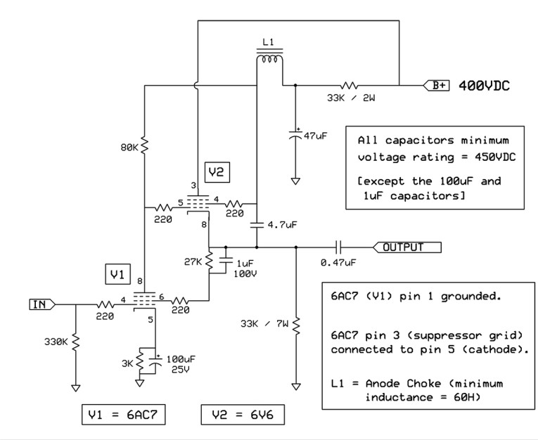
Here are a few notes for every schematic in this article: 1) The heater supply of V1 should be grounded, but the heater supply of V2 should be floating. 2) The DC voltage at the cathode of V2 should be in the neighborhood of half B+. 3) For clarity of the schematic diagrams, the suppressor grid (G3) of every pentode is shown not connected to anything, but do connect G3 to the pentode’s cathode.
Practical Application
I have a friend who is a triode fan, and I modified his stereo single-ended triode (SET) amplifier by converting its voltage gain stage into a mu stage, and he was thrilled with the increased realism and musicality that brought to his amplifier. But I took it a step further and also installed a switch that lets him switch between triode mu stage and Pentriode mu stage operation, but I did not tell him the switch positions—I only told him that the switch gives him two different amplifiers. (Note that such a switch must be switched only when the circuit is OFF and COLD, to avoid sending a large THUMP into the speakers.) I asked my triode fan friend to audition his modified SET amplifier and tell me which switch position sounds best to him. He reported that he prefers the switch position that happens to be the Pentriode mode!
Overall Assessment
In conclusion, listening tests as well as measurements show that Pentriode operation can be superior to either pentode or triode operation. If triode gain is all the gain you need in your application, which is often the case in audio, I believe that the Pentriode may well be the ultimate triode for the reproduction of music!
https://audioxpress.com/article/you-can-diy-meet-the-pentriode
Last edited:

I'm not sure "totally different" really applies. The stage (as shown in your figure 2) is a shunt regulated pentode. This is essentially the topology provided by Cooper in his 1951 paper "Shunt Regulated Amplifiers". It's essentially the general form of Cooper's configuration 2(e). The major difference being that the regulation feedback is provided by slaving the pentode screen grid voltage to the regulator output instead of using an additional impedance to sink additional current in the regulator.
It's an interesting approach to the stage regulation and should be able to source significant drive into a varying impedance. In any event, the circuit should be applicable wherever driving varying impedance loads (as in modulators or class A2 amplifiers) is required. I'm not sure of the advantages in a pure voltage amplification mode however.
It's an interesting approach to the stage regulation and should be able to source significant drive into a varying impedance. In any event, the circuit should be applicable wherever driving varying impedance loads (as in modulators or class A2 amplifiers) is required. I'm not sure of the advantages in a pure voltage amplification mode however.
I've used a similar circuit, with some small changes. The V1 plate pull-up resistor is replaced by a CCS to B+. Then V2 is replaced by a Mosfet follower in similar fashion, except a voltage divider set of resistors is used below the Mosfet Source to drive the V1 screen grid. Bottom divider resistor goes to V1 cathode or to ground. Output is taken from the Mosfet Source. This gives higher output gain than the V1 mu factor and operates the tube at constant current for high linearity. Also the V1 screen grid is operating at lower voltage than the plate, so less screen current is drawn. This works well for lower screen V rated tubes. Been a while since I measured the distortion results for a 12HL7, I think they got posted here somewhere. Seem to recall -60 dB or -70 dB. ( for a curve tracer selected tube ) 12HL7 can have fabulous triode curves by itself, so maybe cheating a little, 12HL7 in triode below:
One could put another Mosfet follower immediately at the V1 screen. to eliminate screen current effects on the divider resistors, but the screen current tends to stay at a constant fraction of the (already constant) plate current. Just arrange the R divider to keep the screen V sufficiently below the plate V.

One could put another Mosfet follower immediately at the V1 screen. to eliminate screen current effects on the divider resistors, but the screen current tends to stay at a constant fraction of the (already constant) plate current. Just arrange the R divider to keep the screen V sufficiently below the plate V.
Last edited:
Interesting circuit. The only disadvantage I see is that you don't eliminate partition noise, like you do when you triode-connect a pentode. Whether that matters depends on the application and on how much partition noise there is to start with.
Running the plate from a CCS pull-up should eliminate most of the audible partition noise. The N Fdbk loop also reduces partition noise. The R divider resistor impedance (versus the screen impedance) could also be adjusted to compensate residual noise. Or a small cap inserted across the top divider R, to sum residual partition noise. Some experimenting required.
Last edited:
Not in my noise transformations. You simply get the full partition noise divided by the transconductance of the pentode as contribution to the equivalent input noise voltage.

The cause of partition noise is that electrons randomly fly to the screen grid or the anode. It can be modelled with a noise current source between screen grid and anode (upper left schematic).
You can split the current source into two fully correlated noise sources to ground, see the upper right schematic. Noise current source B is across a low impedance output, so it does practically nothing.
Noise current source A can be transformed to the input in the usual way, leading to a negligibly small equivalent input noise current source and an equivalent input noise voltage source, just like for an ordinary pentode circuit.
You could get rid of the partition noise by combining the circuit with Frank Blohbaum's patented "best pentode" circuit. You then have to add an extra triode/transistor/whatever, the cathode of which drives the screen grid and the anode of which is connected to the anode of the pentode.
Whoa, wait a minute. What is the date on Mr Blowbaum's patent? That idea has been discussed on DIYAudio 20 years ago. I think the discussion and results were for reducing pentode distortion by re-combing screen and plate currents using (likely) a Mosfet. Same resulting circuit. There are even some curve tracing results on DIyAudio of the resulting curves (which look just like SS devices then). Much of the audio mystique for certain popular audio tubes comes from the removal of tailored screen current from the plate current, so as to remove 2nd Harmonic distortion (and 3rd H in P-P).
Turning hallowed audio tubes into a Mosfet effectively, likely killed the idea back then.
Turning hallowed audio tubes into a Mosfet effectively, likely killed the idea back then.
Last edited:
Here is an example of highly effective use of tailored screen current , JJ KT77:
2nd curve trace, I believe, is of a different pentode (21HB5) -with- the screen current combining. Notice the lack of any kinks.
And 3rd curve trace is of the 21HB5 -without- any fixes:


2nd curve trace, I believe, is of a different pentode (21HB5) -with- the screen current combining. Notice the lack of any kinks.
And 3rd curve trace is of the 21HB5 -without- any fixes:
Last edited:
Frank Blohbaum wrote in Linear Audio volume 0, September 2010, that it was patent pending, DE 102008017678.
Application filed on 8 April 2008, withdrawn 1 November 2016.
https://patents.google.com/patent/DE102008017678A1/de
Application filed on 8 April 2008, withdrawn 1 November 2016.
https://patents.google.com/patent/DE102008017678A1/de
Interesting proposal. In fig. 2 of post 1 the screen voltage of V1 is higher than the plate voltage.
Is this the reason some pentodes work better in this circuit than others, as the author writes ?
In order to ease replies, which program has been used for the drawings, it looks familiar.
Is this the reason some pentodes work better in this circuit than others, as the author writes ?
In order to ease replies, which program has been used for the drawings, it looks familiar.
Which is a CF-driven Hawksford/bootstrapped cascode. Patent filed 3 years before his article was published FWIW.This is similar to the 1987 Audio Research patent assigned to Bill Johnson, which uses a triode cascode
instead of a pentode. The feedback from the follower output goes to the cascode grid.
They also claim several similar, alternative topologies.
In fig. 2 of post 1 the screen voltage of V1 is higher than the plate voltage.
Is this the reason some pentodes work better in this circuit than others, as the author writes ?
I think you will find that the distortion (and likely partition noise too) reduces when the screen V is lower than the plate V.
This could be achieved with some Zener diode or resistors or resistor/current source combination.
I developed a simple circuit that I called the Pentriode.
https://audioxpress.com/article/you-can-diy-meet-the-pentriode
Yes, I think everyone comes up with this circuit at some point in their career. You don't see it in its naked form in old designs because it was more conventional to just run the pentode in ordinary triode-strapped mode, followed by a cathode follower -basically the same end result. You do see some circuits with screen feedback from a cathode, but usually it was decoupled so only the DC was regulated, or where a screen resistor dropped the screen voltage. Nothing new under the sun.I'm not sure "totally different" really applies. The stage (as shown in your figure 2) is a shunt regulated pentode.
Attachments
Last edited:
Is this similar thinking to Multiplied Transconductance Amplifiers, as written about by Frank Blöhbaum in Linear Audio?
In that article he managed to use an octode as part pentode + part triode, and do it all in the single tube (not cheating with tubes containing two parts).
I paid for the excerpts, now I need to recall where I downloaded them!
In that article he managed to use an octode as part pentode + part triode, and do it all in the single tube (not cheating with tubes containing two parts).
I paid for the excerpts, now I need to recall where I downloaded them!
Ultimately, this is just a gain stage follower. If you don't think you can get enough heft out of a 6SN7, why not try a 6BL7 or 6BX7. I also leave the bypass cap off the cathode. Yes it drops the gain but it also increases the bandwidth at least 5 fold. Broader bandwidth less possibility of cold compression. also it has the added feature of degenerative feedback which really help[s the linearity a lot.You Can DIY! Meet the Pentriode
August 4 2022, 10:10
Shortly after my first tube audio article, “The Mu Stage,” was published in 1993 in Glass Audio magazine, I developed a simple circuit that I called the Pentriode. I even wrote a tentative article about the Pentriode in 1995, and I considered submitting it around that time but somehow never got around to it. I finally decided now was the time for me to share a blast from my past as I show you the Pentriode, this time with additional information.
The Circuitry
Probably everyone who reads anything about tube audio circuitry knows that a pentode can function as a triode when its screen grid (Grid 2) is connected to the plate — see V1 shown in Figure 1. When triode connected, many pentodes can be outstanding very linear triodes.
Figure 1: This is a triode-strapped pentode connected to a cathode follower buffer
The Pentriode is formed by making one simple change to Figure 1: Connect V1’s screen grid, not to V1’s plate, but to the cathode of cathode follower (CF) V2—see Figure 2. In Pentriode mode, V1 essentially operates as a triode, but its screen grid current no longer burdens the plate of V1. Instead, CF V2 provides all current to V1’s screen grid. Pentriode mode brings nice advantages.
Figure 2: This schematic shows the Basic Pentriode (circa 1995).
Pentriode mode is not strictly triode mode nor is it pentode mode. It is also not “ultra-linear” (aka partial-triode) operation. I had to come up with an entirely new name for this circuit, and the name Pentriode seemed appropriate. Pentriode mode is definitely most like a triode mode, with the same (or closely the same) mu and gain as the pentode would have in conventional triode connection. In fact, designing a Pentriode stage is as simple as designing a standard triode stage, the only extra part being the addition of a simple cathode follower.
Cathode follower V2 can be any active device, including a triode CF or a pentode CF (my favorite follower for audio — see Figure 3). There are also several other options: You could make a hybrid Pentriode by using a field-effect transistor (FET) source follower in place of V2, or a bipolar junction transistor (BJT) emitter follower, or a Darlington emitter follower, or an insulated gate bipolar transistor (IGBT) emitter follower, or a Sziklai pair follower, or an IC voltage follower, or a current follower, and I’m sure several other follower types. V2 could also be a follower consisting of a vacuum-state device, solid-state device, gas-state device, or any state device.
Figure 3: Here is an improved version of the Pentriode.
By the way, it is my standard practice to use grid stopper resistors for every control grid and every screen grid. Suppressor grids don’t need a stopper resistor. In audio applications, I normally use a value of 220Ω for grid stopper resistors.
Pentriode’s Benefits
It is important to note that some pentodes really excel in Pentriode mode, more so than other pentodes. Some pentodes give even less distortion in Pentriode mode than when the pentode is connected in standard triode connection. It would be nice if we could tabulate a list of the pentodes that excel at Pentriode operation.
It is also possible to make a Pentriode mu stage, which is probably my favorite type of mu stage. It has all the advantages of mu stage operation including wide bandwidth (BW), low distortion, low output impedance, plus the advantages of Pentriode operation. A practical example is shown in Figure 4. With regard to Figure 4: 1) The purpose of the 27kΩ resistor is to drop a few DC volts so that V1’s screen grid voltage is the same as V1’s plate voltage, to closely emulate triode operating conditions for V1. 2) When a 6AC7 tube is used for audio, its heater is best powered by DC. 3) The heater of V1 is pins 2 and 7; the heater of V2 is pins 2 and 7.
Figure 4: The schematic shown here is a Pentriode mu stage example.
Here are a few notes for every schematic in this article: 1) The heater supply of V1 should be grounded, but the heater supply of V2 should be floating. 2) The DC voltage at the cathode of V2 should be in the neighborhood of half B+. 3) For clarity of the schematic diagrams, the suppressor grid (G3) of every pentode is shown not connected to anything, but do connect G3 to the pentode’s cathode.
Practical Application
I have a friend who is a triode fan, and I modified his stereo single-ended triode (SET) amplifier by converting its voltage gain stage into a mu stage, and he was thrilled with the increased realism and musicality that brought to his amplifier. But I took it a step further and also installed a switch that lets him switch between triode mu stage and Pentriode mu stage operation, but I did not tell him the switch positions—I only told him that the switch gives him two different amplifiers. (Note that such a switch must be switched only when the circuit is OFF and COLD, to avoid sending a large THUMP into the speakers.) I asked my triode fan friend to audition his modified SET amplifier and tell me which switch position sounds best to him. He reported that he prefers the switch position that happens to be the Pentriode mode!
Overall Assessment
In conclusion, listening tests as well as measurements show that Pentriode operation can be superior to either pentode or triode operation. If triode gain is all the gain you need in your application, which is often the case in audio, I believe that the Pentriode may well be the ultimate triode for the reproduction of music!
https://audioxpress.com/article/you-can-diy-meet-the-pentriode
Jamie
- Home
- Amplifiers
- Tubes / Valves
- A Totally Different Input/Driver Stage Has Any One Tried It??