Hello all you ribbonmaniacs out there. Look at this...
http://www.hififorum.nu/artiklar/Dahlbergsband/del1/Dahlbergsband.htm
http://www2.hififorum.nu/artiklar/dahlbergsband/del2/Dahlbergsband.htm
It´s in Swedish but you can always look at the pictures. 😀
http://www.hififorum.nu/artiklar/Dahlbergsband/del1/Dahlbergsband.htm
http://www2.hififorum.nu/artiklar/dahlbergsband/del2/Dahlbergsband.htm
It´s in Swedish but you can always look at the pictures. 😀
And a thread about the same project(s):http://www2.hififorum.nu/forum/topic.asp?TOPIC_ID=34799
Not so many pics, but some.
Not so many pics, but some.
Member
Joined 2003
Very clever way of installing the magnets and then rotating them into the gap...seems like a good way to prevent sore fingers! Great workmanship.
No Swedish, so one thing I could not understand from the pictures...is this a multi-element ribbon or a planar?
No Swedish, so one thing I could not understand from the pictures...is this a multi-element ribbon or a planar?
Clarifications please!
The magnets... I see two rows of bar magnets per side, how are they oriented?? What is the purpose of the rubber bead between them? Just to hold them in?
Why no pix of the competed project and/or the ribbon itself?
No pix of the resulting response, etc??
The magnets... I see two rows of bar magnets per side, how are they oriented?? What is the purpose of the rubber bead between them? Just to hold them in?
Why no pix of the competed project and/or the ribbon itself?
No pix of the resulting response, etc??
Hi Bear,
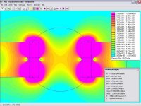
I've attached the FEMM flux density plot from the discussion thread on this ribbon. As you can see, the two magnets on each iron pole side have identical field orientation, just separated by a small gap. As illustrated in the flux density plot, the dual magnets provide a vertically wider, horizontally more uniform field in the center of the gap. This can provide both a more uniform force in this center area, and also a modest self-centering capability. If you look closely at the center flux density plot right at the magnet-magnet gap edge you will see a very large drop in flux which could result in non-linear drive force.
From my past work, one magnet of the same volume at each pole would produce about 20% higher flux density than the two-gapped magnets, and with no edge flux drop. A single magnet, however, would have a greater vertical flux gradient than the two-gapped magnets. I compensate for this on my midrange ribbons by using a wider magnet which also creates a more vertically uniform flux. Tweeter ribbon sonic performance usuallly suffers from a deep cavity.
From my experience, this type of 2-magnet topology is best suited for physically wide, high excursion midrange ribbons. The Apogee Full Range used this on their 2" x 84" midrange ribbon that covered 320-10,000 Hz. It is covered in the Apogee patents. The 2-magnet topology puts the ribbon deeper into the cavity, which is considered non-ideal for tweeter ribbons but an acceptable compromise for midrange ribbons to achieve a wide, strong field with self centering.
There are other techniques for ribbon self-centering.
Attachments
It´s just part 1 and 2. So it´s not finished yet, well his ribbons are but not the construction articles. We´ll have to be patient 😀
if you follow the 17 pages of posts from the fourm you'll find all the pix and response graphs - the text is in Sweedish I presume,
and I can't read it.
LineSource, thanks for the insights... I would think a polepiece of
appropriate design might improve the relationship between the magnets and the gap?
I saw some pix of his ribbon and it looks like an aluminum foil on a plastic film, corrugated... I wonder what he used to affix the foil to the film, and what film he is using...
also... from the postings, it looks to me like the project is finished?
no?
_-_-bear
Hello.
I'm the one responsible for these ribbons and of course, the apogee ribbons has been a great influence when brainstorming this project. I'm using regular household aluminiumfoil (0,0105mm)and 0,002mm mylarfilm for the ribbons. The main reason for the two rows of magnets is too create an even magnetic force over a large distance. The articles will be available in english at my website when they are finished.
Best regards. Bengt Dahlberg
Only in Swedish so far:
http://www.dahlbergaudiodesign.se/
Bengt Dahlberg,
I enjoyed reading about your DIY ribbon. Thanks for putting together a great website.
What did you use to glue the aluminum foil to the mylar?
After you glue and corrugate the film+foil, do the corrugations(pleats) stay in after use or do they start to flatten out due to the mylar stretching back into shape?
Did you try other films besides mylar?
I'm using "3M Spraymount" and that has worked great for me. I 'm using 3 support points for a 4 feet ribbon since a few years and that has eliminated the problem with flatening ribbons. Earlier I used "kapton 30HN" as a carrier but i switched too this very thin (0,002mm) mylar last year. The old ones measured a lttle bit flatter but these ones sound nicer. There is also less "plastic memory" for the aluminum too figth against so the corrugations should last longer. Looks great today (1 year old ribbons) and I have realy tortured them. 600 icepower watts is no problem crossovered at 400hz/2order.
There will be an article about the ribbon manufactoring soon so "stay tuned 😉 ".
There will be an article about the ribbon manufactoring soon so "stay tuned 😉 ".
Bengt Dahlberg,
Thank you for the update on your ribbon construction. I started playing a guessing game.
The weight of the 2u mylar would be about 12%-15% the weight of the Al foil strips. How much weight does the spray adhesive add. I would guess the adhesive sprays on with 20u thickness, and might add 40% the weight of the Al foil strips. The total ribbon weight might be 1.5x the Al foil.
Have you weighed the completed ribbon? What is the total area?
Bengt,
Excellent page (at least the pictures😉 )! You seem to have your ribbon cutting down to a science! Please keep us informred.
Regards,
Denis
Excellent page (at least the pictures😉 )! You seem to have your ribbon cutting down to a science! Please keep us informred.
Regards,
Denis
The area for the uncorrugated ribbon in the example below
is 1500x26,5mm. The length will shrink with at least a foot
with corrugation and mounting.
After doing the math. The weigth of the aluminum for an
uncorrugated 6 foot ribbon 26,5mm wide will be 1gr. The
mylarfilm weighs 0,086 gr . The five 0,5mm strips of
aluminumwaste weighs in at 0,094 gr. The last two take
each other out when compared too a "true" ribbon made
from the same foil and with equal area. The spray adhesive
is added in a very thin layer and if you look closely not even
all of the surface is covered. I'm guesing that it will weigh in
with half the weigth of the mylarfilm. Not an easy task too
weigh these things but maybe there is a decent enough scale
at the university here in town. Maybe that could be a project
for the future, oohhh sh...t I don't need another one 😉 .
Jokes aside, the mass of the finished ribbons is as it should be.
With a thicker plastic film (30HN Kapton) they measure a little bit
flatter from 5-10khz but they do not sound as sweet and they
rool of a little bit faster in the toppregion as well . With a thinner
alufoil 0,006 or 0,009mm the plateaubehaviour will be a problem
that will need adjustment and that was something that I was
aiming for too eliminate. The English version will be out soon
enough at my website, I will keep you posted.
In English
Almost done, just some translation on the second part left (woodworking and internal wiring). It will be finished this week though.
Almost done, just some translation on the second part left (woodworking and internal wiring). It will be finished this week though.
Well done but don't forget to translate the <TITLE> in the pages which still are in swedish.
A good dictionary with also swedish:
http://www.websters-online-dictionary.org/
A good dictionary with also swedish:
http://www.websters-online-dictionary.org/
 Grattis, söta bror! Sällsynt snyggt jobb!!
Any relations between ribbon length and freq.response?
Sensitivity??
What is the approx. price of the magnets from the source you linked??
Best regards from up north!!
Moral circle 😀
Length versus frequency ? I'm not a big fan of short ribbons if you compare them to them to the long ones so I may not be the rigth person to answer that question but I will say no anyway. Width on the other hand has a significant effect on the frequency response.
I'm quite sure that you can figure out how 😉
Sensitivity at least 91 db maybe 92.
Price of the magnets (70x10x6mm) from "Hyab" in Sweden at decent numbers, 10-15skr or a little under 2 $ us.
You are probably not that far away since I live in Umeå Sweden.
- Status
- Not open for further replies.
- Home
- Loudspeakers
- Planars & Exotics
- A Swedish ribbon