Here is a very simple amplifier for desktop use.
It measures 0,001 % distortion or less at 1 kHz wich i believe to some part comes from bad shielding and the generator. Most third tone.
I tested it on ± 15v but it can take a little bit more but ideal for the speakers behind the laptop delivering 10w 8 ohm.
R7 is 1206 10 ppm so i dont think the distortion comes from resistors.

The Layout

And a 3d view. The size is 60 x 40 mm

I wound the coil of 0,75 mm cupperthread on an 8 mm drill. First layer 11 turns followed by 10 and on the top 9. Secured by glue and a pause after each layer.
Remarkable is that it does not work well with OPA 1656.
It measures 0,001 % distortion or less at 1 kHz wich i believe to some part comes from bad shielding and the generator. Most third tone.
I tested it on ± 15v but it can take a little bit more but ideal for the speakers behind the laptop delivering 10w 8 ohm.
R7 is 1206 10 ppm so i dont think the distortion comes from resistors.
The Layout
And a 3d view. The size is 60 x 40 mm
I wound the coil of 0,75 mm cupperthread on an 8 mm drill. First layer 11 turns followed by 10 and on the top 9. Secured by glue and a pause after each layer.
Remarkable is that it does not work well with OPA 1656.

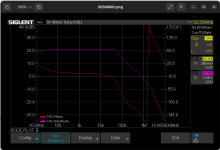
I'm not completely sure but there does not appear to be much if any phase margin - just a simple matter of compensation and a topology revision I think. The abrupt phase reversal around 2MHz is concerning - an indication of possible oscillation?
I think perhaps mistakenly that the 6uH inductor should be outside of the feedback loop not included in it. (fdbk, zobel [boucherot cell] then finally output inductor.)
I think perhaps mistakenly that the 6uH inductor should be outside of the feedback loop not included in it. (fdbk, zobel [boucherot cell] then finally output inductor.)
When the loop gain goes under 0 dB the feedback dont work much anymore.
Anyway when the gain is under 1 it is to small at that frequency to make a self oscillation.
It is a current dump amplifier with the coil inside the feedback loop.
If you replace the R8 with a trimpot it is fascinating to see how the distortion shifts when you raise or lower the value.
The opposite of the output distortion is clearly visable on the oscilloscope at pin 1 or 5 of the IC.
I have a similar prototype here. https://www.diyaudio.com/community/threads/current-dumping-with-opamp.420292/post-7852637
I don't have audio analyzer. I am glad that you are able to measure the THD to confirm the current dumping principle.
I don't have audio analyzer. I am glad that you are able to measure the THD to confirm the current dumping principle.
The plot of post #2 looks like a Bode plot of the closed-loop transfer rather than of the loop gain to me. There is no sharp peaking and the phase jump at 2 MHz is just due to wrapping into the interval from -180 to +180 degrees, so if my interpretation is correct, there is no sign of instability or near-instability.
I wonder where the 80 kHz corner frequency comes from. R7 and C4 should give a first-order roll-off from about 159 kHz onwards, until the circuit runs out of loop gain or the input filter kicks in. I would expect that to occur just above 1 MHz and just below 1.59 MHz, respectively, based on the schematic and some rough calculations.
I wonder where the 80 kHz corner frequency comes from. R7 and C4 should give a first-order roll-off from about 159 kHz onwards, until the circuit runs out of loop gain or the input filter kicks in. I would expect that to occur just above 1 MHz and just below 1.59 MHz, respectively, based on the schematic and some rough calculations.
I think perhaps mistakenly that the 6uH inductor should be outside of the feedback loop not included in it.
I just looked up the QUAD405 schematic and the feedback point is indeed before rather than after the inductor. See R20 and R21 (and L2) in https://liquidaudio.com.au/wp-content/uploads/2017/06/Quad405-2.gif
Use drivers/Darlington's and just bias the output like a normal amp.
The gigantic 100p caps have a lot to do with the distortion and phase margin.
After that you get .0004 % distortion.
And all the AC current doesnt " dump" into one output transistor.
The gigantic 100p caps have a lot to do with the distortion and phase margin.
After that you get .0004 % distortion.
And all the AC current doesnt " dump" into one output transistor.
@ jxdking: You inspired me to do this amplifier so you gave me a lot of fun. Many thanks.
@MarcelvdG: .Misunderstanding. I wrote loop gain not "open loop gain"
I see now that the feedback point is not as in quad. Anyway i can null out the crossover by adjusting R6.
You are right about the crossover frequency. The resistor R7 is texted and correct so maybe i will solder out C4 to measure it.
It is CGO of course but the rolloff frequency shoud be 159 kHz as you noted.
@WhiteDragon: With drivers and bias it would not be a current dump anymore.
I would miss the fun to see how the current dump really nulls out the crossover.
For me it is like a miracle to see how the current dump really nulls out the crossover distortion when i adjust R6.
I have been turning the pot i had there up and down , up and down over and over again just to look at the phenomen.
Now I have under 0.001% distortion with very few components. That should be good enough fo a desktop amplifier.
I have been driving it a few hours with 8 ohm load and my cooler (1,5mm aluminum 70x62mm) gets very hot but no problem with idle current heat compensation. (Bode plots at 5w out)
It is just simple and working.
Now i am going to check it more. For me it is a mistery that the distortion isn´t lower.
The input amp has 0,7v in and its output is only 20mv and the signal looks very clean on the scope.
Distortion is an almost clean third order so i dont think it comes from inside the OP. That should give more of even order.
Input capacitance should give a good part second order but i dont see that. There is about 1k to both inputs. I could try to balance that better. Maybe it is R4 (0805 50ppm/c) or R7 (1206 10ppm/c).
Someone having an idea?
You might try lowering C3. If it stays stable, you put more gain in the loop to decrease distortion.
Jan
Jan
I just checked the capacitors. They are 100 pF. The mystery of the missing 159kHz remains.
100pF means 1,59 Mohm at 1 kHz. The gain is about 1590 than but open loop gain for the OP is about 55000.
So maybe there is something in decreasing C3. But the distortion of the Op? Could it really be third order? Should it be most even orders?
100pF means 1,59 Mohm at 1 kHz. The gain is about 1590 than but open loop gain for the OP is about 55000.
So maybe there is something in decreasing C3. But the distortion of the Op? Could it really be third order? Should it be most even orders?
Assuming you measured the distortion at the output, there are many more factors that determine it than just the two opamps.
You may want to review Vanderkooy & Lipshitz in 'Current dumping, does it really work?' .
Jan
You may want to review Vanderkooy & Lipshitz in 'Current dumping, does it really work?' .
Jan
I have two screenprints here where you can see the distortion undercompensated and over compensated.
The distortion analyser has 180 degrees out.
Blue is tone generator, yellow out from OP1, Green amp out and red the distortion. my 2,5 mm plugins are a problem.
They can cause distortion both at input and output. Anyway it is easy to see the crossover when the amp is overcompensated and its reversed phase in undercompensated amplifier.


Amazing isn´t it.
I have read that article. Maybe i ought to do it again.
The distortion analyser has 180 degrees out.
Blue is tone generator, yellow out from OP1, Green amp out and red the distortion. my 2,5 mm plugins are a problem.
They can cause distortion both at input and output. Anyway it is easy to see the crossover when the amp is overcompensated and its reversed phase in undercompensated amplifier.
Amazing isn´t it.
I have read that article. Maybe i ought to do it again.
It is!Amazing isn´t it.
Did you try changing the cap to home in on the minimum or is that what you showed?
Anyway, Current Dumping does not fully eliminate distortion.
The original idea was to design an amp that needs no bias setting/adjustment/tracking yet delivered performance similar to a usual good class AB.
Not zero distortion. Maybe what you see is as good as it gets.
Edit - did you verify the tone generator distortion?
Jan
No i have not optimised the capacitors.
I was looking at the oscilloscope picture and compared the value there with full scale reading on the distmeter.
With the noise cleaning of 32 averages dist is about 5 ppm.
C5 and C7 is missing on the experiment PCB. Maybe i will order new PCBs but i will try other R4 and R7 first.
The high frequency noise in the distmeter output i believe is from the switch mode PSU in the oscilloscope.
I checked the amplifier with and without the 8 ohm load. No change in the distortion besides that the crossover spikes were gone without load.
I checked the tone generator + distmeter only. Residual distortion 4 ppm.
Used to be 2 so something has happened.
I am going to order a new PCB for a battery sourced tone generator. It will take a week or to because i usually order at least 3 different PCBs every time to save freight cost. The first one had self oscillations but were very promising. Dual lowpass filters instead of wien bridge.
Wit a generator doing 4ppm, an amplifier doing 5ppm is pretty good.
There's a formula to extract the amp dist but it escaped me just now 😎
Jan
There's a formula to extract the amp dist but it escaped me just now 😎
Jan
They are both third order of the same signal so it can just as well be to add as to subtract or any phase in between.
I need better measurement to know.
Thats my main project now so in a year or 2 ...
I need better measurement to know.
Thats my main project now so in a year or 2 ...
Found it. The square of the amp distortion is 25 - 16 (squares) = 9.With a generator doing 4ppm, an amplifier doing 5ppm is pretty good.
There's a formula to extract the amp dist but it escaped me just now 😎
Jan
Therefor the amps distortion is root of 9 is 3ppm.
Assuming no cancellation effects etc.
Jan
@MarcelvdG: .Misunderstanding. I wrote loop gain not "open loop gain"
Neither did I.
In the classical model of a feedback loop, when the gain in the forward path is G and the gain in the feedback path is -H, the open-loop gain is G, the loop gain is -GH and the closed-loop gain is G/(GH + 1). I think your plot shows the combination of the input filter transfer and G/(GH + 1), while I think Kevin interpreted it as -GH.
I see now that the feedback point is not as in quad. Anyway i can null out the crossover by adjusting R6.
If U1B, Q1, Q2, R6, R5, R8, Ch2 is the actual current dumping circuit, then the negative feedback via R6 is actually taken from the right point. The loop involving R7 and U1A is then an extra negative-feedback loop around the current dumping amplifier.
- Home
- Amplifiers
- Solid State
- A small desktop current dumping amplifier