As we all know, operating your tube guitar amp without a proper load (speaker) connected to the output may cause expensive (and extensive) damage.
The problem is made worse by the traditional choice of 1/4" jacks and plugs to connect the guitar amp to its speaker. It's relatively easy to accidentally insert the plug only half-way, or to step on the speaker cord and accidentally pull the plug out of the amp, or, in the confusion before a gig, to simply forget entirely to plug the speaker into the amp. Any of these eventualities can leave your amplifier vulnerable to damage.
For a few years now, I've been using a simple safety load to protect my DIY guitar amplifiers against these sorts of problems. The basic idea is really simple: use a switched mono jack for the guitar amp's output, and wire a high-power 8 ohm (or 8.2 ohm) resistor from the jack's switched contact to ground.
Now if you accidentally operate the amplifier without a speaker plugged in, the power resistor acts as a dummy load, absorbing the amplifier's output power and preventing damage to the output transformer, output tubes, et cetera.
Of course, you also get no sound. In low-pressure situations (playing at home, say) you now investigate until you realize the source of the problem and plug in your speaker. Ideally, the power resistor has a sufficiently high wattage rating to soak up the amplifiers output power until you've had time to find and fix the problem.
Unfortunately, in a higher-stress situation (maybe there's a paying audience and annoyed bandmates impatiently waiting for you to start playing your guitar), you may find it harder to quickly figure out what the problem is. After all, many things can cause a lack of sound from the guitar amp's speaker. Is the guitar volume set to zero? Is it a bad guitar cable? Is the amp volume set to zero? Is the speaker blown? Is the speaker cable bad?
So I added a bridge rectifier, to take the AC signal across the power resistor / dummy load, turn it to DC, and use it to light up an indicator LED. The flickering LED, combined with dead silence from your speaker, will point you at the source of the problem.
It's normal to protect an LED with a simple series resistor, but we have a bit of a problem here. We'd like the LED to come on at the smallest possible voltage (volume from the amp), which requires a small series resistor. But if the amp happens to be turned up high enough, the small resistor won't protect the LED, so it will burn out. Not good.
So I added a JFET to supply current to the LED. The JFET is wired as a constant current source, and what it does is limit the current through the LED to no more than the Idss of the particular JFET you happened to use. If there is barely enough voltage, the JFET acts as a very low-value resistor, allowing the LED to light up at small amplifier powers. If there is sufficient voltage, the JFET operates as a constant current source, safely limiting the maximum current into the LED.
The exact JFET is not critical - use a modern high-brightness LED, along with almost any any N-channel, small-signal JFET you can find, and it will work. Ideally, you want a JFET with a fairly small pinch-off voltage, and Idss between 1 and 10 mA, and just about any of the JFETs typically used in guitar FX pedals will work for this. Old MPF 102s or 2N3819s, or slightly newer 2N5457s or J201s, or even J113s.
A flashing warning light is a useful trouble indicator, but only if you can see it (and happen to look in its direction.) So why not combine it with an audible indication? Simply wire a piezo buzzer across the DC output from the diode bridge, and it will buzz at the same time the LED flashes. You might not hear a buzzer on a noisy stage, and you might not see a flashing LED outdoors in daylight, but with these two different types of warning signals, at least you have a better chance of noticing at least one of them.
The attached schematic shows the plan. J1 is the switched output jack. If nothing is plugged into it, the output of the amplifier is routed to the 8 ohm power resistor R1.
Diode bridge D1 rectifies the AC signal across R1, and this powers led D2, protected by JFET Q1. The same rectified signal also powers piezo buzzer BZ1.
That's about it. If you forget to plug your speaker into your amp's output, this little circuit will save your amplifier, and warn you so you can quickly fix the problem.
This circuit is ideally suited for use with fairly low-power tube guitar amps. You can easily find an off-the-shelf 25W, 8 ohm power resistor to protect the output of a typical 15W guitar amp. But if you have a 200W guitar amp, building a suitable 300 W rated dummy load is a project in itself, and will require a heatsink and the use of many power resistors wired so as to share the power. And when you're done, the result might be too big, heavy, and awkward to build into your amp.
Also, do keep in mind that this little circuit cannot offer you 100% protection. For example, if you plug in the speaker cable at the amplifier output jack, but forget to plug the other end into the speaker cab, your amplifier is still in big trouble, and this circuit will give you no warning, because the problem is at the other end of the cable. 😱
Still, to me, the few bucks it takes to build this circuit is worth the added peace of mind, especially considering what tubes and output transformers cost these days.
-Gnobuddy
Attachments
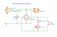
Just to be clear - the triangular symbol I used in the schematic simply means "tube amp schematic goes here". It doesn't represent a solid-state "chip amp"!
-Gnobuddy
-Gnobuddy
Some tube guitar amps use a switching jack to simply short to output to ground if no speaker load is plugged in. Also, flyback diodes are sometimes added at the output tube anodes.
That's where I started, with my first DIY guitar amp build. And it's quite possible that this really is all that's needed.Some tube guitar amps use a switching jack to simply short to output to ground if no speaker load is plugged in.
But some of us have brains that, unless we shut them up, are wired to keep asking "Is there a better or more elegant solution?" As the fictitious detective Adrian Monk used to say, "It's a blessing and a curse." 🙂
Lately I've been stalled on my bigger projects, so I thought I'd share this simple little one, just in case it's useful to somebody.
-Gnobuddy
Self-biased tube amps can simply short the output to ground. (This does foil the LED and buzzer alert.)
Big fixed-bias amps can hurt themselves driving a short.
There's no easy fix for plug in the back of the speaker. On paper we could sense V and I and if not some safe impedance, do something. In practice that's messy.
Although I lived with 1/4" plugs for speakers for many years, I always thought it was a terrible idea. (Plug half-into speaker shorts the amp.) I like to think that today I would only use the SpeakOn connectors.
I agree with you 100% - it's been a terrible idea for about seven decades now. Unfortunately, it's also still a bit of an industry standard. 😡Although I lived with 1/4" plugs for speakers for many years, I always thought it was a terrible idea.
Speakon's are excellent technically, but the connectors are kinda hard to find locally, kinda bulky, kinda expensive, and not usually found in guitar amps or speaker cabs at the kiddie end of the pro-audio pool.
There has got to be a better affordable option out there, but I haven't found it yet. And it won't be a standard, so there will be zero interchangeability.
-Gnobuddy
I think that flyback diodes are the best protection in an open load situation to prevent the tubes or the sockets or the OPT from arcing. Just provide a diode of sufficient reverse voltage capability (two times the plate supply voltage at least) from each tube's plate to ground, with the diode's cathode connected to the plate. Cheap 1N4007's will do for supply voltages up to 500 Vdc. For higher plate voltages use two 1N4007's in series per side.
Best regards!
Best regards!
I'm with Kay here.
I've installed fly-back diodes in all my amps to protect the xformer, tubes and sockets. Though, for the typical 500V B+ I always use *three* 1N4007 in series, just to be safe, this also reduces capacitance on the anodes.
I've installed fly-back diodes in all my amps to protect the xformer, tubes and sockets. Though, for the typical 500V B+ I always use *three* 1N4007 in series, just to be safe, this also reduces capacitance on the anodes.
The trouble is, these protection diodes only clamp negative voltage excursions on the tube plates (to just below zero volts.) They do not clamp positive voltage excursions at all. We just have to hope that the positive voltage swings are no bigger than the negative voltage swings. This assumption does not hold if the waveform happens to be asymmetrical, which it often is when transients are involved....a diode...from each tube's plate to ground
The fact that many commercial tube guitar amps do have such protection diodes, and still routinely fail when accidentally operated without a speaker, shows that such protective diodes are not effective.
Incidentally, the same type of clamping diodes are extremely effective when used with transformerless output stages (usually solid-state), because they can then clamp both positive and negative swings of the output to the corresponding positive and negative voltage rails. One diode from output to negative supply rail, one diode from output to positive supply rail. Done.
But when an output transformer is used, as it is in 99.99% of tube guitar amps, the output plates need to be able to swing to nearly twice B+ during steady-state sinusoidal operation, and will swing far above 2 B+ during transients. And the flyback diodes are completely unable to protect against this, because those plates cannot be clamped to B+. We need them to swing far above B+ for normal operation of the amplifier.
If we had 1000-volt Zener diodes to protect against excessive positive voltage swings, that might have done the trick. But we don't have such devices.
Perhaps suitable metal-oxide varistors (MOVs) would do the trick, but finding the right breakdown voltage to protect the output tubes without hindering normal overdrive might be a bit of a research project - and a somewhat expensive one, if errors are made and output transformers sacrificed as a result.
IMO, a dummy load of the sort recommended in this thread is much more effective protection than the pair of silicon diodes. However, if you like, it is entirely possible to use the diodes as well as the dummy load, since 1N4007s are cheap and take very little space.
-Gnobuddy
You forgot to factor in the transformer coupling action between primaries which actually does keep the positive spike below 2*B+ (with a fudge factor as the coupling isn't 100%, so it's a bit more than 2*B+).The trouble is, these protection diodes only clamp negative voltage excursions on the tube plates (to just below zero volts.) They do not clamp positive voltage excursions at all. We just have to hope that the positive voltage swings are no bigger than the negative voltage swings. This assumption does not hold if the waveform happens to be asymmetrical, which it often is when transients are involved.
Forum member J M Fahey explained it in detail here : How do the diodes protect the OT?
I see no evidence for this, could you give an example reference where properly selected and installed diodes in a decently built amp (taking care to avoid large loop areas in the supply wiring, etc) didn't protect the amp?The fact that many commercial tube guitar amps do have such protection diodes, and still routinely fail when accidentally operated without a speaker, shows that such protective diodes are not effective.
Also, I've personally hardcore-tested this and scoped the anodes (3kV-rated scope probe required!) and the positive voltage stays in bound even with the strongest pulses of arbitrary polarity hitting the PI input. Given the simplicity of the mod it's definitely a most effective one.
...diodes only clamp negative voltage excursions...
What KSTR and JMF say. Positive excursions are clamped at 2.?X the rail voltage.
The "?" is the rise-time of the coupling. For around 10 micro-seconds the far-side is still settling toward zero and not yet clamping.
It is possible a single spike could punch-through. But OT insulation is commercially conservative, and won't punch-through on the first spike. The usual failure is repeated over-voltage causing gradual degradation of the paper/plastic. The rise-time is a fairly small fraction of guitar signal period, so this extends the insulation life considerably.
I do have a gut feeling this leads to "false security". If an OT dies in a week unprotected, and lasts a month with protection diodes, is it really going to live forever? OTOH {cynic ON}, does any modern maker really want your amp to live forever? Or just low failures for 30/90 days, and not-high failures for the few years before they drop that product?
Anecdotal evidence from several techs is that they have serviced Fender amps that fried after being operated without a speaker - even though they have protection diodes.You forgot to factor in the transformer coupling action between primaries
The first time I heard about this was several years ago (circa 2010, I think) on a Super Champ XD thread on a different forum, where one person damaged his amp by operating it without a speaker (he wanted to use the line-out for recording, without making a sound in the room, and didn't know that removing the load was dangerous to tube output stages.) The official Fender schematic for the SCXD shows protection diodes at the output.
That post was followed by posts from several by other people who had experienced similar failures with other amps that included protection diodes. IIRC, at least one was a '65 Princeton Reverb reissue (Note D2 and D3 in the schematic, here: https://www.thetubestore.com/lib/th...nder/Fender-65-Princeton-Reverb-Schematic.pdf
You mentioned I had forgotten about transformer coupling - actually, I had not. The problem is that transformer coupling - especially for a guitar output transformer - only works over a limited range of frequencies. It is quite possible that, with the speaker removed, the amp oscillated at a frequency too high for the transformer coupling to be effective. It is also possible that a big transient at the input (such as unplugging the guitar with the amp powered on) might generate frequencies too high for the OPT windings to be effectively coupled to each other.
Were you also using diodes rated at 3 kV (or more)? It is possible that the failures the techs encounter started with the protection diodes themselves failing, or flashing over.Also, I've personally hardcore-tested this and scoped the anodes (3kV-rated scope probe required!) and the positive voltage stays in bound even with the strongest pulses of arbitrary polarity hitting the PI input.
Incidentally, putting three 1 kV diodes in series does not increase the breakdown voltage to 3 kV, unless you also add parallel resistors to ensure equal voltage sharing.
-Gnobuddy
Uh-huh. We often discuss how imperfect guitar output transformers are, how come we suddenly expect them to be textbook examples of near-100% inductive coupling from DC to daylight?What KSTR and JMF say.
There is no doubt that the dummy load approach works.
There is reason to doubt that the protection diodes work (poll some techs and see what they have to say.)
This thread is about a protection approach that does work, and without requiring 3kV diodes or perfect OPTs.
So why are we instead discussing a different, and apparently less successful, protection circuit?
Keep in mind: realistically, Fender Corp probably uses a pair of 1N4007s only because they are cheaper than a switching jack and a 25W (or higher) power resistor.
-Gnobuddy
Good to have another idea in circulation - thanks for posting (and taking the flack).
My pre-loved peavey triumph 120 has the protection diodes as standard - and vapourised (English spelling) output anode PCB tracks from an event before I bought it.
My pre-loved peavey triumph 120 has the protection diodes as standard - and vapourised (English spelling) output anode PCB tracks from an event before I bought it.
Thanks for sharing one more data point!My pre-loved peavey triumph 120 has the protection diodes as standard - and vapourised (English spelling) output anode PCB tracks from an event before I bought it.
Over the years I've read a number of posts like yours, from many different people, so the anecdotal evidence says that such protection diodes don't always do what they're supposed to do.
I grew up visiting all three libraries in my little town whenever possible usually every Saturday morning. One of them was the local British Council Library, from which I learned English spelling at an early age.
Then I confused myself badly by living in America for a couple of decades, so "cheque" became "check", "honour" became "honor", and the simple elegance of the metric system of units and measurements was replaced by a morass of absurdities.
Now I live in Canada, where the confusion in my head also reigns externally around me: we have the town centre, but also Staples Centers (Staples is an American chain of business supply stores.) The spelling depends on who paid for the building - Canadians, or Americans!
-Gnobuddy
The problem with the switched dummy load ist that you have no control to make sure it is attached. When you have an open circuit after the jack at the amp (cable not plugged in at the speaker end, etc) it will not help. The diodes catch this, as would other means of local (at the tubes/OPT) overvoltage protection (MOVs, spark gaps, gas discharge tubes).
If you want 100% protection in every possible scenario of failure or user abuse, including single faults of the protection means, things get complicated. The amp wiring, and of course the amp design to begin with, must be clean and sober which isn't a given with many products, especially vintage amps.
To help the diodes (or whatever overvoltage protection) it is a good idea to dampen down both the primaries and secondaries with resistors or series RCs (snubbers) to give the flyback voltage something to work on. This unfortunately alters tone but when added in the design stage it can be accounted for. An auto-switched true dummy load for silent recording (withstanding full overdrive power) is useful too (and if you're at it, make it usable as attenuator). A reliable short circuit / overcurrent protection is needed too, and many amps also need a protection for short mains interrupt. Further you want to make shure any standby switch is used properly, so you gotta make an automatic one. Finally, if the amp has selectable mains voltages on the PT, a circuit catching dangerous setting would be nice (US amp brought to the EU and the user forgot to switch to 230V, bang!). One might also add means (series'd fallback fuses) to protect against users installing the wrong fuses or even shorting them when at at gig with no spare fuse at hand. The list is endless....
Last edited:
Once I had a Marshall50W top to repair that the owner destroyed within on minute due to his extremely percussive playing technique. The tubes arced and - game over. It should be mentioned that this happened repeatable WITH the speaker connected.
So I inserted clamping Diodes - to no avail. I measured self resonance of the transformer and then applied an appropriate snubber network across the primary windings. Together with the diodes that fixed the problem.
One more reason for me to stick to SS technology.😉
So I inserted clamping Diodes - to no avail. I measured self resonance of the transformer and then applied an appropriate snubber network across the primary windings. Together with the diodes that fixed the problem.
One more reason for me to stick to SS technology.😉
Who says it´s less successful ? Any statistics backing that? 🙂Uh-huh. We often discuss how imperfect guitar output transformers are, how come we suddenly expect them to be textbook examples of near-100% inductive coupling from DC to daylight?
There is no doubt that the dummy load approach works.
There is reason to doubt that the protection diodes work (poll some techs and see what they have to say.)
This thread is about a protection approach that does work, and without requiring 3kV diodes or perfect OPTs.
So why are we instead discussing a different, and apparently less successful, protection circuit?
You will see more amps with flyback diodes failing than resistor loaded ones for the very good reason that there are 100 or 1000 of the former compared to 1 of the latter.
Like people complaining about "failing Bugera amps" and pointing to a few ones ... like Enzo says, nobody writes about the *thousands* working reliably 🙂
Ummmmm .... parts must be rated for working conditions.without requiring 3kV diodes
1200/1500V peaks are *routinely* driving speakers which are crazy inductive loads, go figure, and that requires *two* 1N4007 in series, so 3 of them in series are needed "just in case" of NO speaker at all 🙂 .
Or a single 3kV one if you want a more compact assembly.
That.Once I had a Marshall50W top to repair that the owner destroyed within on minute due to his extremely percussive playing technique. The tubes arced and - game over. It should be mentioned that this happened repeatable WITH the speaker connected.
Now to the core of the problem:
So I inserted clamping Diodes - to no avail.
WHICH Marshall are we talking about? WHICH Fender? 😉Anecdotal evidence from several techs is that they have serviced Fender amps that fried after being operated without a speaker - even though they have protection diodes.
Fact is that old Fender and Marshall stood much abuse *without* diodes while modern ones explode just by a sideways twisted look, even *with* them .... we should analyze that.
I commercially wind transformers and am often asked to rewind dead Factory installed ones.
So on autopsy I find this:
Old ones (40´s to 70´s) used strong brown to greenish brown to almost black "synthetic" type enamel, applied in a thick layer.
Indestructible or nearly so, testimony being the thousands of surviving amps from that era, which simply for statistical reasons have suffered abuse at least once ... and here they are today. 😱
80´s ones: switched to modern Epoxy coating.
VERY strong, even in thinner layers, you have to burn it with a flame before scratching it or emery paper simply skids on the surface without biting, it is that good and hard. Again very reliable.
90´s on: to save a few cents Manufacturers switched en masse to execrable "self soldering" enamel, so as to save a few cents on assembly.
Enamel **evaporates without residue** leaving behind shiny bright copper at soldering iron temperatures, of course it´s atoms thin.
There lies the current pandemic of blown OTs, real snowflakes.
More than one protection technique should be used uf you want to add layers of safety: diodes and/or snubbers and/or shorting jacks and/or load resistors.
No need for "perfect/ideal" transformers which do not exist in reality, parasite inductance (we call it remanent Inductance, what remains even with secondary shorted, don´t know the current English word for it).
Typically 10X to 20X smaller than main primary Inductance, yet enough to cause uncontrollable peaks with fast rise signals.
Another factor: old "expensive" high interleaving reduced it a lot, modern cheap crummy little or not interleaving maximizes it.
So in a nutshell: anecdotes about OTs failing even with diodes are real, but it´s not the diodes fault, just cheap easy to puncture enamel and cheesy construction.
FWIW I **only** use Electrical Motor rated Class F or H wire, designed not only for frequent overheating (overloaded or stalled motors are an everydayreality) but also high vibration.
Typical smell perceived in Subways is hot electrical insulation, from hardworking big electric motors ... many have been running for 100 years now 😱 ... guess what enamel they use 😛
Add to that cheap thin weak enamel and poor winding specs and you´ll be near the real problem 🙂Keep in mind: realistically, Fender Corp probably uses a pair of 1N4007s only because they are cheaper than a switching jack and a 25W (or higher) power resistor.
Almost forgot: Ampeg was a pioneer using flyback diodes AND still used old style enamel plus high quality winding: I never have one of those to rewind ...I wonder why 😀
Okay, time to summarize:
1) To protect your tube amp output stage from lack of a proper load, use the dummy load resistor and switched output jack as shown in post #1.
Logic says this works better than protection diodes, which only kick in when the voltage across the transformer primary is already dangerously high. Protection diodes are also known to sometimes be ineffective.
2) By all means, also use the protection diodes. They don't do any harm, and may sometimes do some good, and they are cheap.
-Gnobuddy
- Status
- Not open for further replies.
- Home
- Live Sound
- Instruments and Amps
- A safety load for your DIY tube guitar amp