6V6s in Class AB2
Here is a similar version of the amplifier proposed by Miles P back in 2007 (Tee-Vee T00b Amp). This one from the Summer of 2001. Altho the project results were posted on RAT at that time I never authored an article for publication. Real work got in the way. The transient results did appear in the Nov 2003 issue of AudioXpress later as part of another project.
This amplifier was not built with listening in mind. Or as a work of art. It is strictly experimental & satisfied some of my curiosities.
I had certain objectives in mind for this project.
1) PP 6V6s in Class AB2
2) NFB to the upper grids of a differential cascode stage
3) Transient performance of the amplifier while powered by a limited power supply
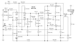
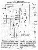
At that time 6V6s were still plentiful. And I had several in my stash. To run in Class AB2 the PP 6V6 loadline has been adjusted to 6.8K running thru a Hammond 125E Universal OPT. The 6V6s are driven by CFs in a 4BQ7. It avoids H-K problems by running on its own 5V supply. The B+ is 338V.
The idea for the internal NFB originated with Bill Perkins of PEARL. On a business trip to Calgary I made a point of visiting Bill. He was working on many projects, one of them included NFB from the output plates back to the screen grids of a earlier stage.
I reasoned that NFB back to the screens would be loaded by the pentode screens, why not try instead the upper grids of a PP cascode stage. The cascode stage is a differential pair of 6BQ7s with a long tail of 100K down to -150V. So the internal NFB is taken from the 6V6 plates. And the resultant internal NFB is ~8 db.
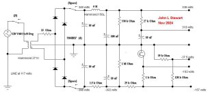
A Hammond 271X power transformer is sufficient to run the 6V6s in Class A. The rectifier is a full bridge of 1N4007 diodes so that both +ve & -ve voltages are available. The +ve filter is a CLC of 10 microF, 5H & 100 microF. The –ve filter CRC of 10 microF, 1.5K & 10 microF. Then 25K & a VR150.
I ran tests both using the amps internal supply & with an external regulated supply.
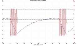
What would happen in the PS if the amp suddenly was required to pass a large transient signal? In some ways this was similar to what happens to a guitar amp when driven hard.
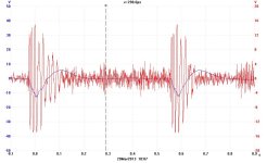
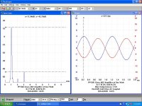
Attached are some of the test results I got recently when I pulled the amp off the shelf for another look. The Scope/SA is a PicoScope 3224. I used a Differential Probe for most of the measurements. For the burst traces the PS sag is the blue trace, the test signal One KHz at 10 Watts.
And it does sound very good. Bench tests are a very good predictor of success.
Here is a similar version of the amplifier proposed by Miles P back in 2007 (Tee-Vee T00b Amp). This one from the Summer of 2001. Altho the project results were posted on RAT at that time I never authored an article for publication. Real work got in the way. The transient results did appear in the Nov 2003 issue of AudioXpress later as part of another project.
This amplifier was not built with listening in mind. Or as a work of art. It is strictly experimental & satisfied some of my curiosities.
I had certain objectives in mind for this project.
1) PP 6V6s in Class AB2
2) NFB to the upper grids of a differential cascode stage
3) Transient performance of the amplifier while powered by a limited power supply
At that time 6V6s were still plentiful. And I had several in my stash. To run in Class AB2 the PP 6V6 loadline has been adjusted to 6.8K running thru a Hammond 125E Universal OPT. The 6V6s are driven by CFs in a 4BQ7. It avoids H-K problems by running on its own 5V supply. The B+ is 338V.
The idea for the internal NFB originated with Bill Perkins of PEARL. On a business trip to Calgary I made a point of visiting Bill. He was working on many projects, one of them included NFB from the output plates back to the screen grids of a earlier stage.
I reasoned that NFB back to the screens would be loaded by the pentode screens, why not try instead the upper grids of a PP cascode stage. The cascode stage is a differential pair of 6BQ7s with a long tail of 100K down to -150V. So the internal NFB is taken from the 6V6 plates. And the resultant internal NFB is ~8 db.
A Hammond 271X power transformer is sufficient to run the 6V6s in Class A. The rectifier is a full bridge of 1N4007 diodes so that both +ve & -ve voltages are available. The +ve filter is a CLC of 10 microF, 5H & 100 microF. The –ve filter CRC of 10 microF, 1.5K & 10 microF. Then 25K & a VR150.
I ran tests both using the amps internal supply & with an external regulated supply.
What would happen in the PS if the amp suddenly was required to pass a large transient signal? In some ways this was similar to what happens to a guitar amp when driven hard.
Attached are some of the test results I got recently when I pulled the amp off the shelf for another look. The Scope/SA is a PicoScope 3224. I used a Differential Probe for most of the measurements. For the burst traces the PS sag is the blue trace, the test signal One KHz at 10 Watts.
And it does sound very good. Bench tests are a very good predictor of success.
Attachments
-
 027 Cascode Amp B.JPG542.4 KB · Views: 165
 -
 IMG_1383 Cascode Amp Bottom A 14W E Flash Labelled.jpg366 KB · Views: 202
 -
 Cascode Amp H.JPG65.8 KB · Views: 207
 -
 2013_03_23_002.jpg67.8 KB · Views: 185
 -
 2013_03_21_001 Peter Gabriel Salsbury Hill.jpg77.9 KB · Views: 125
 -
 Pearl Page 8 30C.jpg104.9 KB · Views: 146

Running on the internal PS the output clips at 19 watts.
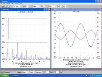
But on a lab supply that maintains the B+ under load the output max is 26 watts.
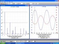
Here are the simple THD tests at three different power levels while running on
the internal supply. The tests were done using a PicoScope 3224 for the measurements.
It is 2-channel, 10 MHz, 12-bit, so 72 db. Sufficient for most tube amplifiers.
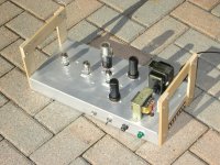
The build uses no PCBs, a waste of time in my opinion.
I'm building only one for experimental purposes.
The use of common terminal strips allows a parts build similar
to TEK scopes of the 60s, real clean & trouble free.
The pulsed test was done using an analogue switch between the SG & the amp in test.
I built the switch as a separate project. It appeared in Glass Audio sometime in 2001.
Feel free to comment & ask questions please.
But on a lab supply that maintains the B+ under load the output max is 26 watts.
Here are the simple THD tests at three different power levels while running on
the internal supply. The tests were done using a PicoScope 3224 for the measurements.
It is 2-channel, 10 MHz, 12-bit, so 72 db. Sufficient for most tube amplifiers.
The build uses no PCBs, a waste of time in my opinion.
I'm building only one for experimental purposes.
The use of common terminal strips allows a parts build similar
to TEK scopes of the 60s, real clean & trouble free.
The pulsed test was done using an analogue switch between the SG & the amp in test.
I built the switch as a separate project. It appeared in Glass Audio sometime in 2001.
Feel free to comment & ask questions please.
Attachments
Last edited:
Your title says 6F6. Is that a typo or are you going to show us a 6F6 version of this amplifier?
Steve
Steve
Not sure how this works out.2) NFB to the upper grids of a differential cascode stage
I went to a Vocational School when I was young, Typewriters were seen a 'Women's Work'.Your title says 6F6. Is that a typo or are you going to show us a 6F6 version of this amplifier
So I leaned a lot about carpentry, sheet metal forming, pulling engines & on & on.
I didn't know how to run a keypad till much later after I had become a P.Eng
So I will attribute my error to the F & V keys being too close on the KB.
Hope that is OK, the post shot out the window to the Satellite before I realized the error.
LOL...I thought that might be the case. But, I was hoping not.
I have a lot of 6F6 tubes and some 10k transformers. I bought them (cheap) after I looked at the triode connected AB2 specifications for this tube.
I have a lot of 6F6 tubes and some 10k transformers. I bought them (cheap) after I looked at the triode connected AB2 specifications for this tube.
Think common plate to previous plate NFB, then go back another stage.Not sure how this works out.
Output plate to a grid on the previous stage results in another phase reversal
so FB leads must be reversed. Then the DC level on the Cascode upper grid
needs to be set.
All part of looking at new & different ways to do things,
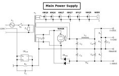
The power supply requirements look quite involved with the -380V, +338 and +150 supplies. Would be interesting to see the schematic for that.
Not to worry, the PS is real simple. Both +ve & -ve rectifiers are used off a
common HV CT winding on the PT. The VR tube is an 0D3/VR150.
The 4BQ7 heater runs off the otherwise unused 5V winding.
The switch labelled (Space) is the standby. Should have been assigned a letter
before I finished the shema. Next time.
Are you still looking for 6LU8 PP help? I built Norman Crowhurst's Twin Coupled
Amp using PP 6LU8s. An article on that was published in Glass Audio.
Attachments
Last edited:
Thanks John!
Not sure if was me that was looking for help with 6LU8. We don't see compactrons so often on this side of the water. But I do like the idea of using non-audio tubes where possible, plus I want to use a VR tube. Unfortunately I am a terribly slow builder.
Not sure if was me that was looking for help with 6LU8. We don't see compactrons so often on this side of the water. But I do like the idea of using non-audio tubes where possible, plus I want to use a VR tube. Unfortunately I am a terribly slow builder.
Not really all that involved. Here's the schemo for the main power supply for Le Renard (attached). The negative rail uses SS doides, and a voltage divider gives the +150V rail.The power supply requirements look quite involved with the -380V, +338 and +150 supplies. Would be interesting to see the schematic for that.
Attachments
- Home
- Amplifiers
- Tubes / Valves
- A Purpose Built Class AB2 PP 6F6 Amplifier