Dear Members,
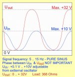
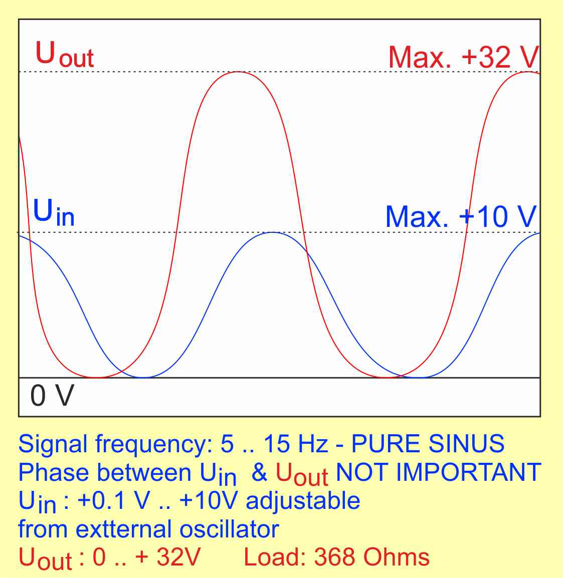
I need to amplify a very low frequency pure sinus signal 5 - 15 Hz sinusoidal
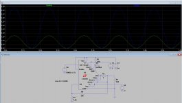
Signal is comming from a signal generator as in attached picture: 1mVpp - 10Vpp, adjustable, ALL POSITIVEI need an output of the signal POSITIVE only,
phase related to input not important.
Load resistance 368 Ohms,
Power Max.: 10W
I need to amplify a very low frequency pure sinus signal 5 - 15 Hz sinusoidal
Signal is comming from a signal generator as in attached picture: 1mVpp - 10Vpp, adjustable, ALL POSITIVEI need an output of the signal POSITIVE only,
phase related to input not important.
Load resistance 368 Ohms,
Power Max.: 10W
Attachments
Single-rail opamp run from 36V into a current-buffering emitter follower might be one way - the load is resistive and to ground?Dear Members,
I need to amplify a very low frequency pure sinus signal 5 - 15 Hz sinusoidal
Signal is comming from a signal generator as in attached picture: 1mVpp - 10Vpp, adjustable, ALL POSITIVEI need an output of the signal POSITIVE only,
phase related to input not important.
Load resistance 368 Ohms,
Power Max.: 10W
By phase not important you mean inverting is as good as non-inverting?
Non usual is an unusual way to say unusual 🙂
....I need an output of the signal POSITIVE only,.....
Add a DC voltage equal to half your peak voltage.
....Load resistance 368 Ohms, Power Max.: 10W
10 Watts in 368Ω is 60.7 Volts RMS, 171 Volts peak-to-peak. That is a high voltage amplifier. At 5Hz a transformer is not very practical. At 300Ω a tube is not very practical. If 10W @ 368Ω @ 5Hz is really what you need to do, it is challenging.
However 0..32V in 368Ω is much less than 10 Watts, so I do not know what you want.
Dear Members,
I need to amplify a very low frequency pure sinus signal 5 - 15 Hz sinusoidal
Signal is comming from a signal generator as in attached picture: 1mVpp - 10Vpp, adjustable, ALL POSITIVEI need an output of the signal POSITIVE only,
phase related to input not important.
Load resistance 368 Ohms,
Power Max.: 10W
Yes the requirements doesn’t make sense. Please correct it. If voltages should be 32v at peak the power would be 2.78w peak. If that is the case the DC coupled amplifier will do this. Nothing special.
While it is easy to get the output to be always positive that might not be the full story.
Does the lower part of the output sine always have to reach to zero volts no matter what the overall amplitude may be? In other words the DC shift is not a constant but has to change automatically with amplitude.
If so then I can't just see an easy way to do that.
Does the lower part of the output sine always have to reach to zero volts no matter what the overall amplitude may be? In other words the DC shift is not a constant but has to change automatically with amplitude.
If so then I can't just see an easy way to do that.
There´s a few problems and contradictions in your request:
1) A direct coupled single supply amp will always have 1/2 Vsupply present at the output, even without signal, over which the sinewave will ride.
So, no datasheet suggestions apply, some have single rail amps but capacitor out.
2) the bottom peak will just meet Ground (what you show in graph) ONLY at full power
3) generator/signal source can easily do that because its level is fixed, but amplifying that to various levels means DC idle voltage must ALSO vary with signal ... is that what you are asking?
4) as a side note, 32Vpp means 11.3V RMS which into 368 ohm mean 0.35W RMS.
Not sure where "10 W" came from.
Clear these important doubts and we´ll be glad to help.
OkI need to amplify a very low frequency pure sinus signal 5 - 15 Hz sinusoidal
IF signal is what you show, single supply amplifier suggestions above do NOT apply.Signal is coming from a signal generator as in attached picture: 1mVpp - 10Vpp, adjustable, ALL POSITIVE I need an output of the signal POSITIVE only
1) A direct coupled single supply amp will always have 1/2 Vsupply present at the output, even without signal, over which the sinewave will ride.
So, no datasheet suggestions apply, some have single rail amps but capacitor out.
2) the bottom peak will just meet Ground (what you show in graph) ONLY at full power
3) generator/signal source can easily do that because its level is fixed, but amplifying that to various levels means DC idle voltage must ALSO vary with signal ... is that what you are asking?
4) as a side note, 32Vpp means 11.3V RMS which into 368 ohm mean 0.35W RMS.
Not sure where "10 W" came from.
Clear these important doubts and we´ll be glad to help.
If looking for 32 volt peak sine wave
wont be much different than a audio amplifier with 35 to 40 volt supply rails.
for LFO or low frequency oscillator
that is the challenge to pass such low frequency
I dont understand why everyone is throwing such a fit.
the signal wont be more than 25 to 28 volts RMS
into 368 ohm load its around 2 to 3 watts.
So asking for a 10 watt amplifier is no big deal for reliability.
The peak values already specified, 32 volts.
So supply rails should be around that 35 to 40 volts.
if the amplifier is AC coupled then the coupling capacitors just need to be extremely large
to pass such low frequency.
No need for single supply, since a output cap would be ridiculous
dual rail
Last edited:
The other issue is how much gain you want. Seems like a voltage gain of 3.2.
As you are only asking for positive voltages out, coupling capacitors are not a good idea.
There are many circuits for DC coupled amplifiers. These often have input capacitors to prevent any DC offset from blowing up loudspeakers.
Seems to me you can meet your requirements with seven transistors or fewer. For the simplest application a single IC amplifier should do. Just omit the input capacitor and if needed apply a bias voltage to the input.
I should point out the circuit is not quite trivial as to DC offset with time and temperature.
You might want to look up a schematic of the HK Citation 12 which was one of the earliest examples of a modern audio amplifier.
Last edited:
Also lookup 'DC restorer' circuits.
DC Restoration
If you replace the diode by an active diode, the baseline will be exactly at the sine wave bottom.
Jan
DC Restoration
If you replace the diode by an active diode, the baseline will be exactly at the sine wave bottom.
Jan
Dont care to over think it.
Just use a single supply LM3886.
input/ output Coupling caps just need to be large to go down to 4 Hz
If the load is only 680 ohms
then the output cap needs to be around 4700u to 6300u
to have decent THD down to 4 Hz
you can figure out how you wanna do pin 7
and the pin 8 mute function
LM3886 needs min gain of 10 to be stable
so your 10 volt input signal would drive it into distortion
Just use a 10K pot at the input to set the needed output voltage.
Amplifier has to be a gain of 10
just use simple transistor like the data sheet for pin 7
I show a 70 volt rail...technically it only needs to be 35 to 37 volts.
probably could just use a LM1875.
wont have pin 7 or pin 8 mute function like the 3886
Attachments
Last edited:
Well that is easier
probably also needs a 100n also across the power pin like C9

probably also needs a 100n also across the power pin like C9
Attachments

Last edited:
So how do you insure that his output signal is always exactly above ground, independent of level, as shown in post # 1?
A 2-part DC restorer would fix that.
Jan
A 2-part DC restorer would fix that.
Jan
Last edited:
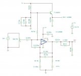
If the input signal is as shown (varying from 0V bottom to 10V top), then wouldn't a DC coupled opamp with a gain of 3.2 automatically give the required offset above ground (output of 0V bottom to 32V top)? Example attached using random high current opamp. Used a V- supply of -2V to allow 0 volts output (won't do rail to rail)
Attachments
How would that work with varying input voltages as shown in post # 1 (1mV to 10V)? Can you show this sim with different input signal levels and no other changes?
DC Restoration
Jan
DC Restoration
Jan
Last edited:
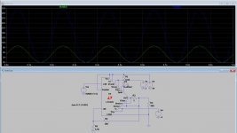
Yes, and you changed the input DC to track the input AC.
That's not what the OP showed I believe; he mentioned the output of a function generator. But maybe he can set the function generator to track the offset, in that case it becomes a no brainer.
I hope the OP didn't run off in despair! ;-)
Jan
That's not what the OP showed I believe; he mentioned the output of a function generator. But maybe he can set the function generator to track the offset, in that case it becomes a no brainer.
I hope the OP didn't run off in despair! ;-)
Jan
There is sufficient info in post #1 to solve it.
An AC coupled input and a diode and a resistor followed by a DC coupled dual polarity chipamp or hefty opamp - done.
But often people (not you) don't read the problem or don't understand it and come up with solutions for a completely different problem! ;-)
Jan
An AC coupled input and a diode and a resistor followed by a DC coupled dual polarity chipamp or hefty opamp - done.
But often people (not you) don't read the problem or don't understand it and come up with solutions for a completely different problem! ;-)
Jan
- Home
- Amplifiers
- Chip Amps
- A NON USUAL amplifier PLEASE HELP