Hello
I have been working on the design of a radically new type of class G amplifier that is technically using Exicon lateral power MOSFET, upto 5000 Watts per channel.
I was considering using Lab gruppen PLM20K44 power supplies for the prototype builds or the much cheaper FP14000 Power supplies.
My requirements are:
+/- 90 Volts
+/- 50 Volts
PSU shutdown control line
To get the additional +/- 50 volts, the transformers may need rewinding with a voltage tap and rectifier?
Any ideas?
I can get the power supplies, i need a schematic drawing to modify them.
Gary
FP14000 Power Supply Board For Replacement,Spare Parts for repairing lab gruppens FP14000 Amplifier-in Amplifier from Consumer Electronics on Aliexpress.com | Alibaba Group
Lab.gruppen PLM20000Q PLM20K44 Power Supply
- Ampman Audio Services - RCF, Lab.gruppen, K-Array spares & accessories
Here is some of the amplifier design spec.
• Full ‘Cold’ short circuit protection below 2 Ohms with automatic retry every 250 mS, option to latch Off requiring a power cycle to reset latch, or option to non volatile latch Off requiring a reset button press on the next power cycle.
• Catastrophic failure detection of blown output stage mosfets
• Catastrophic failure detection of failed PSU capacitor bank, capacitors are in-circuit tested for capacitance, leakage, ESR at start-up
• Catastrophic failure of a mosfet or PSU capacitor does not damage loudspeakers, service light illuminates on front of amplifier
• Multi cycle Inrush current control, IXYS Digital Inrush platform
• No electromechanical relays switch loudspeaker output
• Amplifier powers up with 85 Volt to 264 Volt Universal Input
• Amplifier can withstand a power surge,[electromagnet and amplifier on same circuit breaker]
• Amplifier can withstand a generator Load Dump, [fast switching OFF a high load]
For those who are interested in this somewhat misunderstood older technology.
Class G & H
Another pair of designs engineered with an eye towards improved efficiency, technically speaking neither Class G nor Class H amplifiers are officially recognized. Instead, they are variations upon the theme of Class A/B, utilizing voltage rail switching and rail modulation respectively. In either case, under low demand conditions, the system utilizes a lower rail voltage than a comparably rated Class A/B amplifier, significantly reducing power consumption; as high power conditions arise, the system dynamically increases rail voltage (i.e. switches to the high voltage rail) to handle high amplitude transients.
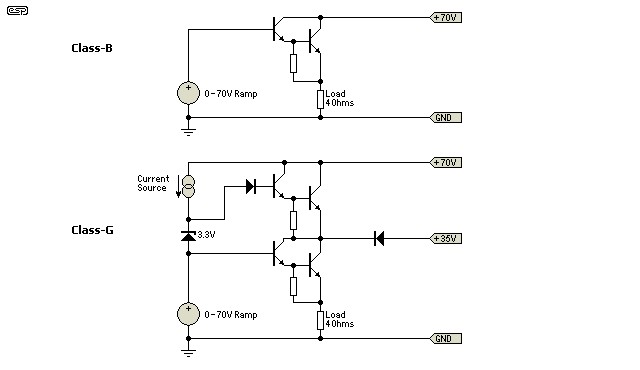
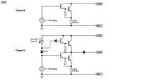
A comparison of Class B and Class G topologies (left; image sourced from sound.westhost.com) and the Outlaw Model 2200, a compact, cool running 200W Class G amplifier (right).
So what’s the drawback here? In a word: cost. Original rail switching designs utilized bipolar transistors to control the output rails, increasing complexity and cost. These days, that is often reduced to an extent with the use of high current MOSFETs to select / vary the rails. Not only does the use of MOSFETs further improve efficiency and reduce heat, but fewer parts are required (usually one device per rail). In addition to the cost of rail switching / rail modulation itself, it’s also worth noting that some Class G amplifiers utilize more output devices than a typical Class A/B design. One pair of devices will act in typical A/B fashion, fed by the low voltage rails; meanwhile another pair is held in reserve to act as a voltage booster, only activated as the situation demands. At the end of the day, because of these additional costs you’ll usually only see Class G and H associated with high powered amplifiers where the increased efficiency makes it worthwhile. Compact designs may also leverage Class G / H topologies as opposed to Class A/B given that the ability to switch to a low power mode means they can get by with a slightly smaller heatsink.yes, check out my other post to find out how to do class G the proper way like a audio pro.
& don't forget the voltage limit on a lateral mosfet is 200V, this would mean that one would have +/- 90 Volt rails with a class AB design at a push, class G series connected mosfets would have much higher outer rail voltages how about +/- 400V ?
& don't forget the voltage limit on a lateral mosfet is 200V, this would mean that one would have +/- 90 Volt rails with a class AB design at a push, class G series connected mosfets would have much higher outer rail voltages how about +/- 400V ?
- Status
- Not open for further replies.