Hi
Could anybody help me to build a excellent pre-amp for my sub woofer?
I'm using this circuit as my sub's amp:
230W / 400W Mosfet Amplifier
and this circuit as my sub's low pass filter:
I'm getting a excellent sound of my sub when I connect it to my PC but when I use different audio sources like DVD player or TV and etc It doesn't have the same sound when I use it with my computer
I want a pre-amp or even an low power amp so I can match this sub's amp with any kind of audio sources
I used LM386 but it has some DC voltage in its output
So if anyone could help me with it I'll appreciate it
Could anybody help me to build a excellent pre-amp for my sub woofer?
I'm using this circuit as my sub's amp:
230W / 400W Mosfet Amplifier
An externally hosted image should be here but it was not working when we last tested it.
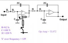
and this circuit as my sub's low pass filter:
An externally hosted image should be here but it was not working when we last tested it.
I'm getting a excellent sound of my sub when I connect it to my PC but when I use different audio sources like DVD player or TV and etc It doesn't have the same sound when I use it with my computer
I want a pre-amp or even an low power amp so I can match this sub's amp with any kind of audio sources
I used LM386 but it has some DC voltage in its output
So if anyone could help me with it I'll appreciate it
Your PC has gain that you can control/volume control.
DVD or TV is going to the crossover? If so employ a preamp. Hook your DVD
or TV output to a preamp and the output of the preamp to your crossover.
DVD or TV is going to the crossover? If so employ a preamp. Hook your DVD
or TV output to a preamp and the output of the preamp to your crossover.
Your PC has gain that you can control/volume control.
DVD or TV is going to the crossover? If so employ a preamp. Hook your DVD
or TV output to a preamp and the output of the preamp to your crossover.
thanks 6BG6GA
but as I said before I'm looking for this pre-amp and I need some info about it like its schematic
Last edited:
Why not add gain to the first opamp in the filter like this.
Use say 10K for the feedback resistor and select the other resistor to give the gain required. With TL072 (FET) there should be no DC offset problems so I haven't shown a cap in series with the other resistor. The switch is just to switch between original gain (x1) and the new gain. Or use a pot to set the gain.
Use say 10K for the feedback resistor and select the other resistor to give the gain required. With TL072 (FET) there should be no DC offset problems so I haven't shown a cap in series with the other resistor. The switch is just to switch between original gain (x1) and the new gain. Or use a pot to set the gain.
Attachments
Why not add gain to the first opamp in the filter like this.
Use say 10K for the feedback resistor and select the other resistor to give the gain required. With TL072 (FET) there should be no DC offset problems so I haven't shown a cap in series with the other resistor. The switch is just to switch between original gain (x1) and the new gain. Or use a pot to set the gain.
Thanks a lot
I'm gonna check that
Hi Mooly
I tried what you told me about increasing the first op_amp's gain
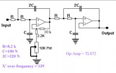
and here's the schematic that I used :
But when I turn the pot to increase the gain (to around 2) the out put sound changes to a loud continuous voice (like Hummmmmmmmm)
I also increase the gain to around 5 but it makes it worse
What shall I do now????
Thank you so much
I tried what you told me about increasing the first op_amp's gain
and here's the schematic that I used :
An externally hosted image should be here but it was not working when we last tested it.
But when I turn the pot to increase the gain (to around 2) the out put sound changes to a loud continuous voice (like Hummmmmmmmm)
I also increase the gain to around 5 but it makes it worse
What shall I do now????
Thank you so much
Is the opamp running on dual (split supplies) ? I assumed it is but better check.
If so it should work... if not you need a cap in series with the pot.
If so it should work... if not you need a cap in series with the pot.
Before you do anything make absolutely sure you have the pot connected properly and that it does go to signal ground.
If you measure on DC volts the output of the opamp in question (with no signal) the output should be 0.00 volts. It should remain so as the newly added pot is turned.
The cap in series with the pot would be an electroylitic of at least 47uf for extended low frequency response. You shouldn't need it though. Measure the above first and lets see if anythiong is going on.
You won't get any gain in the circuit unless you change a couple of resistor values.
The 10k resistor which feeds the pot should be lower in value. Perhaps 2.2k.
The pot should be 10k. The 100k pot in series with the 10k shunt leg will give only a limited amount of level control.
The 10k resistor which feeds the pot should be lower in value. Perhaps 2.2k.
The pot should be 10k. The 100k pot in series with the 10k shunt leg will give only a limited amount of level control.
Attachments
Valid point from Frank regarding the range of gain available and how the control behaves.
You have to find out why it's behaving as it does first though... so check the DC levels.
Are you sure you haven't connected the pot to an incorrect point with you saying it hums loudly as it is turned ?
You have to find out why it's behaving as it does first though... so check the DC levels.
Are you sure you haven't connected the pot to an incorrect point with you saying it hums loudly as it is turned ?
Yes, I'm completely sure about the pot's connections (exactly like the schematic)
I'll check the DC on output in an half an hour and let you know
thanks again
I'll check the DC on output in an half an hour and let you know
thanks again
OK, probably be tomorrow when I next look in.
The pot needs to go to those cap grounds as shown on your original diagram.
Make sure you have NO input connected when you measure the voltage initially. Be careful measuring, a slip could cause a huge output and damage the speaker.
If the voltage is zero (as it should be) then reconnect the input and measure again.
As shown your circuit is DC coupled and so any offset from before the opamps would be amplified by the opamps and if bad enough cause the output to swing toward one of the rails.
Just trying to cover all bases 🙂
I checked the circuit and as I said before there was no problem with it.
and about the DC voltage on the output I should say that it's around 0.00 (audio input disconnected)
but I measured the AC voltage on the output and found out that when input was not connected the AC voltage was around 0.00, but when I connected the input to computer there was some AC voltage in the output (Even without any music played) that this AC voltage could reached up to 9.00 Vac (when I increased the gain of course)
So Mooly what do you think?
I think it's very strange 🙂 is what I think !
Without having it all on the bench in front of me it's difficult to generalise so lets go back a bit and confirm everything along the way...
Before we do that have you tried it with another signal source such as a portable CD etc or ipod ? Something that's fully isolated from any mains connection (grounds). Is it still not right with that ?
Also if apply a short to the input (shorting the input to ground) the AC and DC output voltages should remain at zero as the pot is rotated.
Did the circuit work OK with the computer before my suggested modification ?
We need to prove that so if you just lift the 10K that goes to the pot (post #8) than that will bring the circuit back to "original" gain. The 10 K between output and inverting input can be left in place.
Now recheck those output voltages with and without it being connected. There should be no AC or DC at the opamp output (no signal no output).
Before we do that have you tried it with another signal source such as a portable CD etc or ipod ? Something that's fully isolated from any mains connection (grounds). Is it still not right with that ?
I'm going to check this with my sell phone now.
Did the circuit work OK with the computer before my suggested modification ?
Yes, I have one circuit that I'm using right now as my sub's filter and also when I turn this circuit to the original circuit (the circuit I have problem with) it works very well
We need to prove that so if you just lift the 10K that goes to the pot (post #8) than that will bring the circuit back to "original" gain. The 10 K between output and inverting input can be left in place.
yes, I did this and circuit work just like the original circuit without any problem and any differences.
I'm going to check this with my sell phone now.
Lets see what that shows...
Yes, I've got the same response with my cell phone (AC voltage when input is connected but no music or sound is played)
- Status
- Not open for further replies.
- Home
- Source & Line
- Analog Line Level
- A excellent Pre-amp