Some time ago I made a couple of full range ribbons, 110 cm long, of which I described the construction in another thread of mine. Since then I have listened to them both dipole mounted and in closed box and with different types of music, and I must say that I liked them much more in closed box. In addition to being less critical with respect to positioning, closed box ribbons are definitely superior when listening to percussion instruments. The response to transients is exceptional, everything perfect, except the spatiality. By spatiality I mean perceiving the reproduced sound as if it came from instruments actually present in the room. I have found that those who say that tall ribbons should be listened to as if they were headphones are right, with the listening point between the two sources. The side effect that summarizes what, in my opinion, is the defect of long ribbons is this: Listening to the music while seated, the orchestra and the singer are located in a certain position, but when you get up, the orchestra and the singer are also raised . This effect evidently derives from the directionality in the vertical plane of the tall ribbons, an effect that I mistakenly considered positive in all respects, believing, based on what I had read, that the reflections from the walls were an effect to be avoided. I changed my opinion and now I believe that the reverb from the walls is not only natural but necessary for the effect of spatiality. Following this idea I want to experience listening with an almost point-like source, while maintaining the sound quality of the ribbon, and for this I started the design and construction of a curved ribbon.
Of course I am aware that a thrue ribbon cannot be curved, so I will resort to the side suspension construction, which I have used in my previous ribbons with good results. The principle to follow in the construction is simple: The ribbon is held in place by the lateral suspensions, while the terminal connections serve only as electrical connections without exerting any mechanical force.
Of course I am aware that a thrue ribbon cannot be curved, so I will resort to the side suspension construction, which I have used in my previous ribbons with good results. The principle to follow in the construction is simple: The ribbon is held in place by the lateral suspensions, while the terminal connections serve only as electrical connections without exerting any mechanical force.
Discarded the idea of a very small ribbon, as it would only be a tweeter, the possibility of a curved ribbon remains. Expecting that the construction would not be easy but above all to approximate the point source I limited the length of the ribbon to about 30 cm, developing it on an arc of about 90 °. Having set a maximum excursion of +/- 4 mm this driver can be full range only at very low volume, but to judge the effect it may be enough. Later, to have greater volumes, I will evaluate the convenience of coupling it to a woofer, with a low crossover frequency, or to build a longer one, with the unknown, however, whether a greater radius of curvature would drastically change things. Suggestions in this regard will be welcome.
I started with the study of the magnetic motor, and after several simulations I chose the following configuration
Bx smooth
The space inside the dashed rectangle in the center is where the ribbon will move, while the space on the left and right between the rectangle and the pole pieces is reserved for lateral suspensions.
Attachments
I also drew the structure in 3D (with some slightly different details)
Rib_curvo
And I obtained the graphs of the magnetic field on a longitudinal central line and a transverse central line
Bx longitud
Bx transv
The value of the field is low, but still a little higher than in the ribbons built previously.
Rib_curvo
And I obtained the graphs of the magnetic field on a longitudinal central line and a transverse central line
Bx longitud
Bx transv
The value of the field is low, but still a little higher than in the ribbons built previously.
Attachments
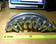
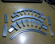
So, having bought the iron, I put my hand to the miter saw and the arc welder and I built the polar expansions and the magnetic field closures. After flattening the contact surfaces to the magnets, I galvanized everything to avoid corrosion problems.
iron elements
I made the return conductors with 0.4 x 6 mm copper strips and glued them with epoxy under the paper-insulated pole pieces.
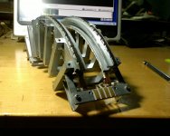
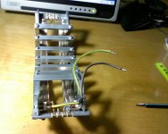
After having assembled everything with neodymium magnets grade 38, dimensions 5 x 10 x 25 and having put the copper contacts, previously gilded, here is the result:
engine
engine 1
motor 2
Now I am building the ribbon, 27 mm wide, of 36 um thick aluminum, divided into 4 strips 6 mm wide each, supported by 12 g / m2 model aircraft paper glued with very diluted bostik. On the sides of the ribbon I glued 2 strips of fabric, 30 g / m2 chiffon, for the side suspensions, 3 cm wide to be trimmed later. This chiffon is made of polyester and therefore thermoformable. Up to this point the construction is the same as for a straight ribbon
Rib phase1_v
I corrugated the tape to give it longitudinal elasticity, as I want it to behave like a pulsating cylinder and not like a rocking cylinder.
I built a wooden form to lay the tape on it, with the same curvature of the pole pieces and with the desired profile for the corrugations of the side suspensions
Shape_h
iron elements
I made the return conductors with 0.4 x 6 mm copper strips and glued them with epoxy under the paper-insulated pole pieces.
After having assembled everything with neodymium magnets grade 38, dimensions 5 x 10 x 25 and having put the copper contacts, previously gilded, here is the result:
engine
engine 1
motor 2
Now I am building the ribbon, 27 mm wide, of 36 um thick aluminum, divided into 4 strips 6 mm wide each, supported by 12 g / m2 model aircraft paper glued with very diluted bostik. On the sides of the ribbon I glued 2 strips of fabric, 30 g / m2 chiffon, for the side suspensions, 3 cm wide to be trimmed later. This chiffon is made of polyester and therefore thermoformable. Up to this point the construction is the same as for a straight ribbon
Rib phase1_v
I corrugated the tape to give it longitudinal elasticity, as I want it to behave like a pulsating cylinder and not like a rocking cylinder.
I built a wooden form to lay the tape on it, with the same curvature of the pole pieces and with the desired profile for the corrugations of the side suspensions
Shape_h
Attachments
Curved ribbon part 3 A true Curved levitating ribbon without spacers ? - YouTube
Trying to levitate ribbon with DC.
Bernt "Båndsei"
Trying to levitate ribbon with DC.
Bernt "Båndsei"
Last edited:
Thanks Bandsei,
I had seen other Joppe Peelen videos, but I missed this one. The idea is brilliant and I thought about it, but in my case it is difficult to apply, as it is based on the balance between the electromagnetic force and the recall forces of the ribbon. In the video of Joppe it worked because it uses the magnetic configuration of planar drivers, where B decreases monotonically with the distance from the magnets, but with the magnetic configuration of the "true ribbon" B decreases away from the center in both directions, so the equilibrium would be unstable. Perhaps it could be used with an automatic position control, but it is all to be experimented. I will continue to insist on lateral suspension, as they have the advantage of allowing for an extension of the low frequency response.
Anyway thanks for reporting
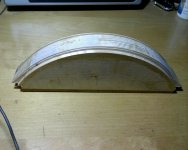
During the project the biggest difficulty I encountered was how to attach the lateral suspension to the pole pieces. In the ribbons made earlier I had simply used diluted bostik, but here I couldn't due to the narrow channel shape of the pole pieces. I didn't even want to use double-sided adhesive tape, because those that give guarantees of durability are difficult to remove in the event of a ribbon change. The only passable idea I've come up with is to use adhesive Velcro, attaching a hook-like strip to the fabric, and a hook-like strip to the pole pieces.
So I laid the ribbon over the form and used copper wires to force the fabric to follow its profile. I heated the fabric with the heat gun, then attached the Velcro hook strip to the outermost part of the fabric. Since the adhesion was not good as the fabric released lint, I first had to impregnate the fabric with liquid bostik (only in the part that had to adhere to the velcro), and then the velcro adhered well. Having freed the ribbon from the shape, I moved on to the chemical section to nickel the aluminum where it had to make contact. And here I realized the mistake, because I had to do it first of all. In fact, by handling the tape to put it in the baths, the corrugation is damaged and the shape of the side suspensions has also lost precision. This was an unexpected mistake, however I patiently remedied it, revising the corrugation and redoing the side suspensions. Here is the assembled ribbon
Ribb on
Attachments
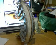
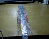
I am not satisfied with how it turned out, because the curvature is irregular, the ribbon is not exactly in the center of the magnetic field and furthermore the corrugations of the lateral suspensions are too deep for the +/- 4 mm of expected displacement.. However, before doing another I want to do some measurements.
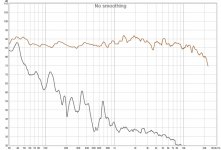
This is with 0.2W and calibrated umik placed 6cm from the ribbon
SPL C0
The SPL graph is not bad, considering that the driver was resting on the table without any tricks, but the distortion starts to rise below 800 Hz, while I expected that it would be acceptable from 200 Hz and up. Maybe it is due to the construction defects that I found, but I will only know if I can make a precise ribbon. I calculated that the SPL at 1W, 1m should be around 80dB which is absolutely low, but still good for my purposes.
I also did listening tests, in comparison with my long ribbons, with music and singing without low frequency content (so as not to stress the ribbon), and I found confirmation that the directivity in the vertical plane it's not good for the presence effect, at least in the conditions of my room. .
Now I will start building another tape by correcting the mistakes I made in the first one.
Attachments
- Home
- Loudspeakers
- Planars & Exotics
- A curved ribbon