This is an adaptation of Rod Elliot's capacitance multiplier. I am filling a couple of needs with this circuit, which will be powering a 500W mono class-D amp into a 4 ohm load.
Since I have a couple of 500VA transformers but the secondaries are a bit too hot for the class-D amp's overvoltage limit I want to be able to limit the maximum voltage that the cap multiplier can produce. I use a set of zeners for this purpose.
Rod Elliot's original design is for a modest output class-A amp, and uses a single darlington for each rail. I am powering a different type of amp, need higher output power and current capabilities. I've used multiple pass transistors in parallel with low R current sharing resistors to help balance the load. I don't have any experience designing and building this kind of thing, but it seems logical to do it this way and I would rather not use a MOSFET. I have also used higher input and output capacitance, 10,000uF per rail, of which I have a few with a sufficient voltage and current rating.
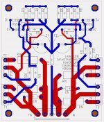
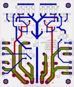
Here is the circuit that I am using to sim the performance of the supply:

This is pretty similar to Rod's circuit, with zeners Z1-Z4 replacing resistors in his circuit, the increased input and output capacitances, and the multiplicity of TIP3055 and TIP2955 devices. I show a 30A bridge but I will use a 50A bridge in the real circuit, mounted on the heat sink.
I see pretty good performance in my simulations under a variety of loads. Under no-load conditions, the zeners form a voltage divider with R1&R2 or R3&R4 and limit the voltage at the base of the BD140 and BD139 transistors. This lets me for instance limit the rail voltages to +/-87V with very low ripple - the first bank of capacitors (C1, C2) is sitting at around +/-92V with the mains at 120VAC and it doesn't change if the mains voltage rises - it's a nice hard limit. With increasing load current being drawn, the output voltage falls along with the average voltage on C1 and C2 and remains only a few volts below the minimum in the ripple. At very high output power (e.g. 600W) the difference increases a bit to about 6V. When I only used a single TIP3055/TIP2955 this was much larger, likely due to the current demand approaching the limit of those devices. This is one reason why I decided to parallel a few of them (four in the circuit as shown). I assume I need low tolerance 0.1R balancing resistors in order to parallel these correctly...
I'd love to get some feedback on this design and where I may be way off, if I am pretty much on target, or any tweaks that might be appropriate.
-Charlie
Since I have a couple of 500VA transformers but the secondaries are a bit too hot for the class-D amp's overvoltage limit I want to be able to limit the maximum voltage that the cap multiplier can produce. I use a set of zeners for this purpose.
Rod Elliot's original design is for a modest output class-A amp, and uses a single darlington for each rail. I am powering a different type of amp, need higher output power and current capabilities. I've used multiple pass transistors in parallel with low R current sharing resistors to help balance the load. I don't have any experience designing and building this kind of thing, but it seems logical to do it this way and I would rather not use a MOSFET. I have also used higher input and output capacitance, 10,000uF per rail, of which I have a few with a sufficient voltage and current rating.
Here is the circuit that I am using to sim the performance of the supply:
This is pretty similar to Rod's circuit, with zeners Z1-Z4 replacing resistors in his circuit, the increased input and output capacitances, and the multiplicity of TIP3055 and TIP2955 devices. I show a 30A bridge but I will use a 50A bridge in the real circuit, mounted on the heat sink.
I see pretty good performance in my simulations under a variety of loads. Under no-load conditions, the zeners form a voltage divider with R1&R2 or R3&R4 and limit the voltage at the base of the BD140 and BD139 transistors. This lets me for instance limit the rail voltages to +/-87V with very low ripple - the first bank of capacitors (C1, C2) is sitting at around +/-92V with the mains at 120VAC and it doesn't change if the mains voltage rises - it's a nice hard limit. With increasing load current being drawn, the output voltage falls along with the average voltage on C1 and C2 and remains only a few volts below the minimum in the ripple. At very high output power (e.g. 600W) the difference increases a bit to about 6V. When I only used a single TIP3055/TIP2955 this was much larger, likely due to the current demand approaching the limit of those devices. This is one reason why I decided to parallel a few of them (four in the circuit as shown). I assume I need low tolerance 0.1R balancing resistors in order to parallel these correctly...
I'd love to get some feedback on this design and where I may be way off, if I am pretty much on target, or any tweaks that might be appropriate.
-Charlie