Does anybody know about the 811A internal resistance
I try to establish that datas via anode curves diagram
througt grapical method but the results are too much
differs each others that make me very suspicious...
Thanks a lot...
I try to establish that datas via anode curves diagram
througt grapical method but the results are too much
differs each others that make me very suspicious...
Thanks a lot...
Somewhere around 10k I think.
µ is extremly high so it behaves more like a pentode than a triode, sort of.
Planing on using them in an A2 amp?
Been there, done that.
µ is extremly high so it behaves more like a pentode than a triode, sort of.
Planing on using them in an A2 amp?
Been there, done that.
Yes I am planing to begin seting one amp
with a 811A...
I even found some cores by "Wasner"
for the output trans...
Actualy I have problem to aproach to
primar inductivity that is becoudse i
need to know about the Ri of the 811A
What is Your experiance you said that You build a amp with...
with a 811A...
I even found some cores by "Wasner"
for the output trans...
Actualy I have problem to aproach to
primar inductivity that is becoudse i
need to know about the Ri of the 811A
What is Your experiance you said that You build a amp with...
Thank You Fuling...I will post the settings
of my topology...soon
But on the first site I foun that
You feed the 811 from the cathode...
My intension is to put the input transformer first...
of my topology...soon
But on the first site I foun that
You feed the 811 from the cathode...
My intension is to put the input transformer first...
Hi
I set the 811A at :
Ug = +15 V
Io =60 mA
Ua = 900 V
RL = 10468 ohm (10.5 Kohm)
with estimated :
Pa = 54 W
Po =12.875 W
H2 = around 0%
-A = 34.33
Ig = aroud 5 mA
Cdyn = 204 pF
that requires 5960 ohm input R for -3db at 131KHz or 19541ohm for -3db at 40KHz...
The problem is that I could not calculate the Ri from the anode curves datas and
with that value of Ri calculate Req of the output stage stage...
And when I dont have the Req proper calculated i simply could not calculate
primar inductance of the Output transformer for desired low frequencu response...That is all...
Ri is nonlinear with voltage, operating points, load, and frequency- modeling it as a pure resistance is not terribly accurate.
Of course SY...
But I have to start with something...
I am planing to try a litle simulations with a PSpice (I found a subcircuit for the 811A
tube )...
What I heard about the 811A tube from people who done somewhat with is :
That 811 in presence of DC signal behaves like decreasig the Ri rapidly...
and that is Ig increasing until the 20-40 mA ???
The best thing to start with is the minimum resistance that the grid will present. I'd do some measurements (pulse excitation, please!) to determine, for the tubes you're actually using, what the Ri is at the maximum expected drive voltage. That can be done with a pulse generator, an amplifier, a series resistor, and a scope.
Maybe it is the best way
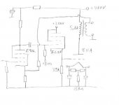
to determine Ri is to make real circuit
set the +Ug for the desired point
controling the Ia for the desired value
and put for R_Load a powerful resistor_pot.Changing the Vbattery and the value of RL until we get the same
Voltages at the RL and Ua with of course
desired Ug and Ia...
Than the value of Ri will be the same as the RL_pot...?
But that is little bit complicated
requires the 50-100W pot.
and the about 2000V controlable Pover suply...
requires the 50-100W pot.
and the about 2000V controlable Pover suply...
Need more detailed information, please.
I am fairly interested in building up a SE by using 811a as power tube. Can you give me more details about the features of this tube and related schematics? Thanks a lot.
Fuling said:Here´s the basic topology of my amp:
Triode wired E81L input stage, EL86 cathode follower direct coupled to 811A grid. I can post a more detailed schematic within a couple of days if anyone´s interested.
I am fairly interested in building up a SE by using 811a as power tube. Can you give me more details about the features of this tube and related schematics? Thanks a lot.
I finished my 811A monoblocks quite some time ago and used them for a while. Unfortunately I had some serious problems with mechanical noise from various parts, mostly from the rectifiers for the driver stage (PY82).
I decided to tear them apart and rebuild them on MDF breadboard "chassis" using different rectifiers.
This was some months ago and since then the project has more or less died, simply because of all the work involved.
Just a couple of days ago I made some new plans for this project.
This time it would be a simplified version using solid state rectifiers and a mosfet buffer instead of the cathode follower.
The biggest problem would be to fit the filament power supplys inside the chassis (no monoblocks this time).
I don´t think 811A´s can be AC heated without severe hum problems.
If you want to use these tubes, I´d say go ahead.
They don´t sound bad at all, but they require some negative feedback to get the output impedance down and they´re a bit of a mess to drive because of the grid current.
Fortunately they don´t require much voltage swing, only 50V p^p or something. Nothing a grunty cathode or source follower can´t handle.
A better solution might be to use interstage transformers, but suitable ones ain´t cheap.
One word of warning: A bit of timing seems necessary in the startup process: if the grid voltage is applied when the filament is applied before the plate voltage (when the filament is warm) the grid current might reach dangerous levels.
This might be a problem when using slow warmup rectifiers for the
B+.
Thank you for your thorough introduction. It seems directly heated tube rectifier will be good option for it can get heated quickly to add high voltage to the anode of 811a, or FU811, its soviet and Chinese equivalent. I have a schematic as following that uses 5z3p as rectifier. 5z3p is the Chinese version of western style 5U4G, directly heated double diode. Welcome your comment on this design. Note: 6N9P=6SL7.
Attachments
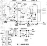
That schematic (never seen that particular one before) looks prefectly sound to me. Maybe the operation point seems a bit "cold"to me, I ran my tubes at about 430-440V and 100mA into 5,6kohms load.
Can´t tell if one is better than the other, though.
That amp is fully DC-coupled, good for the sound but bad if some part goes south somewhere and takes the rest with it.
Maybe the risk is smaller in this kind of amp because of the positive bias. If the output tube looses its bias it will turn off instead of going wild.
5U4 or equivalents should be fine as long as they can handle the voltage.
For the cathode follower, use something with relatively high current capability and gm. 6V6 would not be my first choice, I picked EL86 and it worked fine.
That schematic looks familiar.
If all the voltages and currents corresponds correctly there is no need for a cathode resistor on the driver stage, since the 811 grid will act as one.
If all the voltages and currents corresponds correctly there is no need for a cathode resistor on the driver stage, since the 811 grid will act as one.
Generally speaking, how large would the grid current of 811a would be? I mean, would it be a little bit wasteful to use 6L6G, a tube with modest current handling capacity as its driver? How about EL84? It has high S value and sufficient plate current capacity?
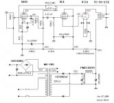
Schematic with EL84
Kenneth,
Here's a schematic with a EL84, I built this one.
Due to the low plate voltage output power is 5W max.
Sounds pretty good (and looks good too).
811A & EL84
and here's a collection (zip file) of 811A schematics :
811A collection
Greetings,
Jim
Kenneth,
Here's a schematic with a EL84, I built this one.
Due to the low plate voltage output power is 5W max.
Sounds pretty good (and looks good too).
811A & EL84
and here's a collection (zip file) of 811A schematics :
811A collection
Greetings,
Jim
- Status
- Not open for further replies.
- Home
- Amplifiers
- Tubes / Valves
- 811A tube internal resistance ?