Hi everyone!
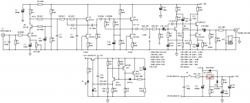
Here's the circuit I plan to build for casual 78RPM listening. I've designed it so that it gives a good sound for all of my discs for straight off the disc listening. It features a 3 pole rumble filter set to 35Hz a low pass filter set to 10KHz and all the eq. options you'll ever need. 🙂
I got creative with the topology as it's been a while since I built a discrete design, as this isn't a distortion critical application (although the distortion performance should be fine) I decided to build an all discrete phono preamp for this purpose.
The front end is a BJT cascoded low noise JFET (2SK170) gainstage with a flat gain of 37dB. The bias is set with a potentiometer (to 14V for the most headroom) as I've found the variation in drain current with these FETS to be a little to great to go without.
This is then fed into a low pass 10KHz 3 pole Butterworth filter, this may seem a bit extreme but the vast majority (97% from my restoration experience) of my discs don't have a true response past this point and there's some pretty nasty noise past that point anyway. This then feeds into a 3 pole high pass Butterworth set to 35Hz, once again, I've very rarely seen any information on the spectrogram that wasn't rumble past this point so it's a good idea to get rid of this part of the spectrum too 😉. Both filters are based on BJT emitter followers loaded with JFET current sources. The filters may not seem necessary but the simple fact of the matter is that there really isn't anything worth listening too without noise reduction past this point and with a flat eq (common for pre 1950 pressings) the gritty HF portion is pretty unpleasant and distracting. The same can be said with low frequency noise. 78s are generally not 'hifi' so what we're after is the most pleasant sound possible 😛. It's only common sense 😎
The high pass filter feeds a 6dB low pass filter which is used to apply the treble cut part of the correct eq. curve. Pretty straightforward. 😀
The bass boost is done using an active shunt feedback stage in the usual way. The collector load of Q7 is bootstrapped to increase gain (and thus linearity). R24 and R25 set the output bias voltage to about 14V. This is then followed by Q8 to the output which is decoupled by C18. Feedback is taken after decoupling to improve frequency response (it doesn't make too much of a difference but it saves a capacitor that would be used to separately decouple the feedback network). The output stages load driving ability is improved by configuring it in a similar way to the 'White cathode follower' circuit popular with tube designers. As the circuit is mono the load is going to be a parallel of two stereo inputs to the main amplifier. This will present a minimum load of 5K so rather than increasing the current of the CCS (which would have made it less linear) a couple of resistors and capacitors allow it to be modulated to improve the efficiency of the output stage while also slightly improving the linearity of the follower. Win win 😉
So there you have it. A good way to listen to your 78s in all their warm crackly glory on your top notch HiFi. I'll be building the circuit within a week and will post pics plus audio snippets.
It runs off a 24V supply. I'll post schematics of that and the muting circuit tomorrow.
Attachments

Last edited:
Improvements + power supply and muting circuit
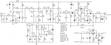
Here's the circuit + a few improvements. I've raised the supply rail to 28V (as there's no point wasting the excess created with a 24V transformer 😉 especially when it could be used for extra headroom). I've adjusted a few biases to take advantage of this. The first gainstage can now do 10V peak to peak. More than enough for a MM cartridge with gain taken into account.
The power supply is a simple LM317 type with improved ripple rejection via C23 set to 28V.
The muting circuit contains a simple discrete 12V regulator to drive the muting relay. Fairly straightforward, a divider checks the voltage across the pre regulated part of the power supply, when the voltage is higher than about (while the preamp is on) 30V Q12 steals current from the base of Q13 causing it to stay off. This allows current to flow into the base of Q11 creating a reference voltage for Q10 to follow opening up the relay and illuminating the power indicator LED. C21, R40 and D2 make up the necessary time constant (about 6 seconds or so) which makes sure that the circuit has time to stabilise before the output is ready. When the supply voltage drops as the circuit turns off Q12 turns off in turn causing Q13 to conduct and shunt current away from Q13 while quickly draining the C21 so that it the preamp should be turned on again rapidly then it will give the audio circuit another 6 seconds to stabilise. This ensures that under no condition will turn on noise ever be heard 🙂.
I've modified the shunt feedback stage slightly to allow better approximation of the eq. curves while keeping the low frequency response predictable.
That's all for now. Time to start building 😀
Attachments
 for efforts and sharing
Thanks Zen Mod, not many people do really so not really expecting any replies. Just want an online record TBH, if one other person builds it then it'll be worth the trouble.
Having said that quite a few people are frustrated with the cost of commercial ones, so who knows? 😉
Having said that quite a few people are frustrated with the cost of commercial ones, so who knows? 😉
nice to know that someone is really bothering with listening , building for and restoration of these gems
having some experience with capture and sound editing ( in previous life ) , I'm able to appreciate passion and energy involved in
having some experience with capture and sound editing ( in previous life ) , I'm able to appreciate passion and energy involved in
Yeah, if you want to then check out some of the stuff I do on soundcloud and youtube...
https://www.youtube.com/watch?v=VES_ez8lU1c
https://soundcloud.com/monty78pig
Gonna be uploading some more soon 😀
https://www.youtube.com/watch?v=VES_ez8lU1c
https://soundcloud.com/monty78pig
Gonna be uploading some more soon 😀
Simulated results for the various treble selections:
An externally hosted image should be here but it was not working when we last tested it.
Thanks Jack 😀. Could you get me a distortion figure too?
Just checked my boards, I'd made that very mistake with the 2SK170😱! Simple fix though so not too much hassle. Thanks for the heads up!
Just checked my boards, I'd made that very mistake with the 2SK170😱! Simple fix though so not too much hassle. Thanks for the heads up!
Btw, I think you've forgotten that the terminals across the bass boost are shorted for flat bass operation. The gain should be 37dB, not 57dB.
I changed C12 to 22u so that the response of the tone network will be flattish and fed the signal into this node, skipping the low pass and high pass filters. Here's the response of the two networks on their own:
I think that the nomenclature for the bass boost networks should be something like 39nF||220k rather than the "+" sign -- am i correct?
An externally hosted image should be here but it was not working when we last tested it.
An externally hosted image should be here but it was not working when we last tested it.
I think that the nomenclature for the bass boost networks should be something like 39nF||220k rather than the "+" sign -- am i correct?
Lastly -- here's an FFT assuming 10mV 1kHz -- and putting in the low pass and high pass filters. The red is the output of the first stage, the aqua trace is output :
An externally hosted image should be here but it was not working when we last tested it.
Perhaps make the output stage a conventional T3,T4,T5 feedback network.
Doing this you could also have an exact RIAA curve, as well as the older curves.
R1=137K, R2=11.8K, R1//R2=10.864K
Thus the feedback resistor remains 148.9K
For the bass boost, assume that C1=2.2uF making T3 300mS
T5 = R2*C2; C2=T5/R2 thus
6.5kHz ~25uS C2=2.1nF
5.0kHz ~32uS C2=2.7nF
etc
T4 = (R1//R2)*(C1+C2)
700Hz ~ 228uS; C1=20.9nF
etc.
The T3 values change a bit, but would not appear to be critical.
For the R1/R2 values shown, the RIAA curve would have
C1=23.2nF
C2=6.4nF
An externally hosted image should be here but it was not working when we last tested it.
Doing this you could also have an exact RIAA curve, as well as the older curves.
R1=137K, R2=11.8K, R1//R2=10.864K
Thus the feedback resistor remains 148.9K
For the bass boost, assume that C1=2.2uF making T3 300mS
T5 = R2*C2; C2=T5/R2 thus
6.5kHz ~25uS C2=2.1nF
5.0kHz ~32uS C2=2.7nF
etc
T4 = (R1//R2)*(C1+C2)
700Hz ~ 228uS; C1=20.9nF
etc.
The T3 values change a bit, but would not appear to be critical.
For the R1/R2 values shown, the RIAA curve would have
C1=23.2nF
C2=6.4nF
That's an idea, but you'd end up with a much lower combination of curves. I'd prefer separate controls for each part of the curve as you can create lots of different settings. Also I prefer the 1uF cap as opposed to the 22uF one as the bass response is already limited by the 35Hz high pass filter.
You can use DIP switches and work out the capacitor matrices so that there are an enormous number of permutations.
When C1 becomes large (2.2uF is convenient as there are WIMA caps which fit the bill) only the Treble Cut (C2) becomes effective.
When C2 becomes quite small (10pF) only the Bass Boost becomes effective.
And when C1=23.2n and C2=6.4n you should get a quite good fit to the RIAA curve. Pretty easily done as illustrated below.
You also get rid of the insertion loss associated with R19,20 etc.
When C1 becomes large (2.2uF is convenient as there are WIMA caps which fit the bill) only the Treble Cut (C2) becomes effective.
When C2 becomes quite small (10pF) only the Bass Boost becomes effective.
And when C1=23.2n and C2=6.4n you should get a quite good fit to the RIAA curve. Pretty easily done as illustrated below.
An externally hosted image should be here but it was not working when we last tested it.
You also get rid of the insertion loss associated with R19,20 etc.
- Status
- Not open for further replies.
- Home
- Source & Line
- Analogue Source
- 78RPM Heaven - a discrete multicurve phono preamp for your shellac!