So far everyone has been stumped and I thought this would be a good place to ask. Here's my original post on another forum:
Now, the issue is either something happened to the tube during transit or another guess was:
I emailed my tube preamp manufacturer (Dared MC-7P) to see if there would be an issue running a 7 pin 6V6GT/G instead of a 6 pin 6V6GT but they have not gotten back to me so far.
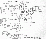
I do have a schematic for my preamp but aside from seeing where the 6V6 is in the power section of the schematic, I have no idea what I'm looking at.


Any ideas?
So I finally decided to try out the Raytheon 6V6GT/G and Holland Amperex 12AX7's I have. I was already using the same 12AX7 tubes, I just wanted to test these out. I took all the tubes out and dusted off the preamp chassis and tube tops. I then put all the tubes back in using the new ones. I turned on the preamp and then POP! out of the speakers, this happened maybe two seconds after I fired it up. Startled the crap out of me. I VERY quickly turned the preamp off. I noticed that the Ratheon 6V6GT/G slowly lit up after I turned on the preamp up until the bang/pop where it got brighter much quicker. What's the deal here? The Raytheon tested better than NOS on the sellers tester. I put the RCA 6V6GT back in and all is well, the preamp is fine and all eight tweeters are fine. The Raytheon has an extra pin that the RCA does NOT have.
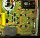
I took this picture zoomed in too far to be holding the camera, I can't stay still enough for a crisp picture at this much zoom. The RCA is on the right, Raytheon on the left.

Now, the issue is either something happened to the tube during transit or another guess was:
I 100% don't know (sorry), but sometimes tubes have an "extra" pin -- and sometimes it can cause a problem IF a component manufacture happened to use that pin's location on the socket as a "tie point" for other circuit components. It's an admonition one will see sometimes in the tube manuals.
I emailed my tube preamp manufacturer (Dared MC-7P) to see if there would be an issue running a 7 pin 6V6GT/G instead of a 6 pin 6V6GT but they have not gotten back to me so far.
I do have a schematic for my preamp but aside from seeing where the 6V6 is in the power section of the schematic, I have no idea what I'm looking at.


Any ideas?
My apologies, I didn't think the pictures were resized that small. Hopefully these aren't gigantic.


Any ideas?
That piccie is blurry, but it looks like the extra pin is added to the #1 spot. That puts it right next to the cathode pin which is at a high potential to ground. The cause of this problem could very well be that someone got lazy and used the "unused" socket connection as a tie point of convenience. This was done a lot back in "the day", though it's not a very good idea, especially when the 6V6 is being used in an unconventional manner. It was presumed this type would see duty as an amp, not a series pass device.
You also don't say what "it" is that gets brighter. Is it red plating, or is it the filament? Maybe attach a photo of the wiring so's we can get a better idea of what's going on here.
You'll have to excuse my tube ignorance but "it" is the part that normally glows red after the tube has been on for a few seconds which can be seen from the top and bottom of the tube.
These are the only internal pictures I have of the preamp from when the previous owner upgraded the capacitors to Auricaps. I believe the only tube socket that can be seen from underneath is the 5U4G rectifier socket.
Outside shots

These are the only internal pictures I have of the preamp from when the previous owner upgraded the capacitors to Auricaps. I believe the only tube socket that can be seen from underneath is the 5U4G rectifier socket.
An externally hosted image should be here but it was not working when we last tested it.
An externally hosted image should be here but it was not working when we last tested it.
Outside shots

An externally hosted image should be here but it was not working when we last tested it.
Might be this:

Do you have a picture of the bottom wiring of the tube?
I believe the "S" relates to the shielded can on a metal tube connected to pin one and then to ground,,, the GT has no shield, however some glass tubes also have a pin one... the proper spec sheet should mention IC or NC...
Last edited:
1-8 pins are shorted on the PCB but should not be a problem since the pin-1 has no connection inside tube.
You can check if the pin-1 has some shorts in the Raytheon tube to other pins by an ohm-meter.
You can check if the pin-1 has some shorts in the Raytheon tube to other pins by an ohm-meter.
I believe the "S" relates to the shielded can on a metal tube connected to pin one and then to ground,,, the GT has no shield, however some glass tubes also have a pin one... the proper spec sheet should mention IC or NC...
Right.
I searched for Raytheon 6V6 data sheet but got no return.
Let's try forum-size pictures.
As noted, 6V6 traces are visible.
Pin 1 probably should have been left open at the socket, but that is not your problem.
It sounds like a heater-cathode short. When cathode sits at 350V, that could happen. The designer wisely gave the 6V6 its own heater winding. My *inclination* is that there should/could be a resistor from cathode to heater, to "pull-up" the heater as cathode voltage rises. However I can not make this guess fit with your observed symptom.
I don't see why you need any "special" 6V6. It's not in the audio path. It isn't working near what a 6V6 could handle. It IS an odd (but not very-odd) use of a 6V6. Most tube testers could miss a heater-cathode insulation flaw, and in most 6V6 circuits it would do no harm.
Attachments
I have one of these on my bench now. I’m not a tube guy, but trying to help a friend. Same type of regulator issue. FJosh, did you find the issue? With just the tubes necessary for the power supply, I’m getting +450vdc from the output of the 6V6. Ideas?
Sometimes a regulator of this type refuses to start because the other plate of the error amp is tied to the B+ out.
And for a regulator with limited gain of the error amp such as this, DC on the error amp heaters is a waste of time & $$$.
If the cap at the output terminal is too large some regulators might be unstable & oscillate.
C19 & C20 are too large, the following LC filter & regulator should be sufficient to remove any ripple.
But on a PC board there are few fixes possible.
Whoever designed this has not done many toob regulators. 😱
There's a few issues I can see, one is as mentioned powering the error amp with DC heaters is daft, the heaters for this valve should be referenced to high voltage to keep heater cathode V max within spec,therefore the heater wndg should be at something like 70 - 100v ish.
See attached for more info on such supplies.
Andy.
See attached for more info on such supplies.
Andy.
Attachments
Thank you for the pdf Andy, much appreciated. I'm certainly open to modifying this circuit to make it more stable. jhstewart9 mentioned that C19 & C20 were too large, can you recommend a better value? I've got some 50uf/350v and 10uf/350v in my stash.
No worries, happy to help. I built circuit 2 but with a VR100 as the voltage reference, I experienced some instability which was caused in part by my forgetting to add C2, I also added a "snubber" across the VR100. I did a video here -
about debugging/stabiising the regulated supply.
If you look at the schematics in that PDF you'll see they used a 4u7 cap, your 10u/350v should do the job though to be honest it might not be needed at all. Try it and see and monitor the regulated OP for ripple etc.
Andy.
PS, don't know WTF is happening with the link, I was only after posting a link not a big video window thing. Computors, stick with valves.
- Home
- Amplifiers
- Tubes / Valves
- 6V6 Regulator Issue

