Hi all,
Quite a while back I built a preamplifier that I am pretty sure I learned about on this forum. I think at the time I had built an Aikido linestage and was interested in preamps. Anyway, I built one designed by a member here, Poindexter, that he had christened Moebius and used 6T4 valves. I think a version was available as a commercial preamp and got good reviews at the time. Anyway, the preamp had been in storage for many years now, and in the course of a tidy up, I pulled it out for a look and to check it over today.
Suffice to say, it is clear from revisiting this old build that I have learned a reasonable amount about building in the last decade! After a fair bit of tidying up functional but janky wiring, improving grounding and redesigning the HV supply, its sounding very capable now. I'll give it a soak test for a while to make sure its stable.
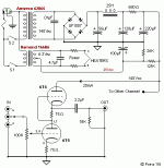
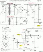
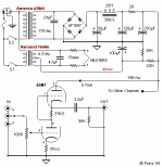
Anyway, none of that is why I'm posting here, the real reason is that no matter how I searched here I couldn't turn up a schematic or a build thread. I eventually found the schematic on a Polish forum, and thought I'd post it here - along with the question - have others here built this pre? Anyone still got it in use?
Fran
Attachments
I dunno. I know I'm using DC for my build (6T4). I think the idea of the dropping resistors was the run the heaters slightly under 6.3V. Maybe?
The reactance of 10 μF. at 60 Hz. = 265.3 Ω. The Z that the 6.3 VAC is working into is truly complex.
Although not commonly encountered, radios that used a cap., instead of a resistor, to bring a series heater string into alignment with the AC mains voltage were built.
Although not commonly encountered, radios that used a cap., instead of a resistor, to bring a series heater string into alignment with the AC mains voltage were built.
I built a Moebius way back and I used the circuit shown above with 6AQ5 tubes. I don’t recall Poinz mentioning other tube options but I wish he had because the 6AQ5 were very microphonic. I also don’t remember any details about the sound quality except that it didn’t push the right buttons for me. I quickly moved on to other designs.
Its funny, I can't recall any other versions of it being mentioned!! I think I must have had a conversation with him in a thread, and decided to build it. I bought 6T4 valves, because there is no way I would have had them, and I think I have spares as well. The 6T4 are slightly microphonic, but only very slightly so, and only when tapping the chassis with a knuckle.
I've had it playing now for hours and all seems OK with it, everything seems stable and working correctly. I don't think I have much more to do with it now other than listen.
I've had it playing now for hours and all seems OK with it, everything seems stable and working correctly. I don't think I have much more to do with it now other than listen.
You want less AC at a filament, use matched series resistors in each leg.
Do not use a cap across the 6.3V to reduce the filament voltage.
Perhaps the cap was there in hopes of reducing RF interference, but. . .
Unless you are very near to the US Navy's 1 Mega Watt 15kHz transmitter (In which case, you better move elsewhere).
Do not use a cap across the 6.3V to reduce the filament voltage.
Perhaps the cap was there in hopes of reducing RF interference, but. . .
Unless you are very near to the US Navy's 1 Mega Watt 15kHz transmitter (In which case, you better move elsewhere).
....but. . . Unless you are very near to the US Navy's 1 Mega Watt 15kHz transmitter....
About 80 miles airline distance.
VLF Transmitter Cutler - Wikiwand
Since the dang thing covers the earth, 80 miles is not far.
PRR,
Thanks!
I am glad I do not have any such transmitter like that near me.
And, I think it covers just a little distance underwater.
I remember some early experiments with probes in the earth, and using the earth as a dividing resistor for direct through-the-earth audio communication.
Where there is a will . . .
Last edited:
You want less AC at a filament, use matched series resistors in each leg.
Do not use a cap across the 6.3V to reduce the filament voltage.
Perhaps the cap was there in hopes of reducing RF interference, but. . .
Unless you are very near to the US Navy's 1 Mega Watt 15kHz transmitter (In which case, you better move elsewhere).
Is there any clue in the way that the 6T4 and 6SN7 schematics have 4.7uf across the heater windings, but the 6AQ5 uses 10uf?
Transformers usually use around 0,1uF antiparasitic across primary , in this case there is one across the secondary high voltage and a big one across filament . For sure it is not for droping the filament voltage 😀
If it is useful or not ... who knows , but I doubt you gain something ,
If it is useful or not ... who knows , but I doubt you gain something ,
@Depanatoru - Yes - I'm using DC heaters anyway so this discussion doesn't matter much to me! But it would be interesting to know what Poindexter had in mind when designing it.
If it is antiparasitic it doesn't matter if you use DC for heaters .
High voltage is DC too and still has one across the winding .
But I would use it across the primary , the correct way to do it .
By the way , the author has drawn that big , dubious role , capacitor for filament but forgot capacitors across the high voltage bridge diodes ...
High voltage is DC too and still has one across the winding .
But I would use it across the primary , the correct way to do it .
By the way , the author has drawn that big , dubious role , capacitor for filament but forgot capacitors across the high voltage bridge diodes ...
Last edited:
OK, mystery solved as to Poindexters original reason for the cap across the heater windings:
Most details are in this thread:
What preamp should I build?
He says in a few different posts that he heavily favoured the 6T4 over other valves.
Fran
If you would like to use a regulated (and thus DC) heater supply, with its attendant cost and complexity, go ahead on; I have no objection. I will say that with my slightly filtered (see the capacitor across the heater circuit, to filter out the hi-frequency rubbish possibly coming in from the wall AC), I am getting on the average 0.03mV (thirty microvolts) of hum + noise on the output of my circuit, which seems about half tube rush. I have other more important places to spend the client's money than on this spec right now.
Most details are in this thread:
What preamp should I build?
He says in a few different posts that he heavily favoured the 6T4 over other valves.
Fran
- Home
- Amplifiers
- Tubes / Valves
- 6T4 Moebius resurrection


