If it were me, I'd not waste most of the B+ lighting up a glow tube, putting the amplifying stages at poor positions on their operating curves. But maybe this is intentional, like a guitar pedal. Separately, it's always a good idea to include cathode stops for follower outputs driving the cold cruel world outside the box. A few hundred Ohms between the output cathode and output jack helps to damp potentially resonant tanks that can form. Maybe ideally right at the cathode pin, but really anywhere will do the job better than nothing.
All good fortune,
Chris
All good fortune,
Chris

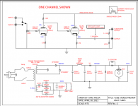
110k seems much too high a plate resistor for the 6SN7 gain stage in this circuit. If you insist on a B+ of 150 volts, a 30k plate resistor will give decent results and the complete circuit will draw a total of about 5.4 mA from the power supply. With a plate load of 110k, the power supply draw will be roughly half of that, not the 5.5 mA shown on the schematic.
Remember VR90 can only deal with 30mA, the rest are good for 40mA.
Doesn't matter here, but good info to keep in mind. Bypass the VR tubes with 1M resistors so they strike easier if you do stack them.
Personally, I'd just ditch the VR and modify it to use a TL783...
Here's my version for 330V or so out from 400V in. It'll be cleaner than the entire supply in the schematic the OP shared and cost less than the price of the choke alone. I build with R1=560R, R2=100R, C1 and C2 100µF
Modify the resistor ratio to change the output. This is good for about 50mA if it drops 75V total. More with a larger heatsink.
I made PCBs for this if you want one...
Last edited:
If DC is a requirement at the signal level where this cct operates, better start looking for other problems.
Ordinary AC heating should be AOK. And avoids some unnecessary complication.🙂
Ordinary AC heating should be AOK. And avoids some unnecessary complication.🙂
Except when a 150W SMPS costs 20% of the cost of the 150VA transformer 🙂I use AC heating on nearly everything unless I already have a DC source available for other things, or if its for microphone or low RIAA levels. Too convenient and super easy to do right.
There is DC on the input volume control. This will result in noise when it is turned. It also is apparently a variable bias for the input triode!
The output capacitor has 50 volts on it but is rated for 450 volts.
The filament power supply has a voltage dropping resistor before the rectifiers, used after the rectifier allows the 10,000 uF capacitor to be changed to two 4,700 uF capacitors one before the resistor and one after. This will give about 20% greater filtering.
There is a choke in the main DC supply. Even if you raise the rails a resistor will give better filtering at a much lower cost. It also can be used to drop the voltage a bit more and reduce the load on the regulator tubes.
A 10 Henry inductor at 120 hertz is equal to around 7,500 ohms of resistance. A resistor of 7,500 ohms will provide the same filtering and drop the raw voltage by less than 40 volts. So you can increase this to say a 15,000 ohms and 5 watt resistor. Better filtering and much lower cost. Better still use 7,500 ohms there and change the next 1,000 ohm resistor to 7,500 ohms. (One watt should be fine then.)
Also I would not use a 6SN7 but instead the 12AU7! Lower cost same results.
Last edited:
12AU7 will yield worse distortion numbers in a good circuit, why hobble the circuit further with one when the conditions are already not great? 😕Also I would not use a 6SN7 but instead the 12AU7! Lower cost same results.
Better choice for cost would be a 6CG7/6FQ7 as it's the same characteristics as the 6SN7.
Yeah, but that's too voodoo for some folks, hard enough to get tube guys to use diodes for rectification, and you want them to trust transistors?!?! 😆Except when a 150W SMPS costs 20% of the cost of the 150VA transformer 🙂
NB: That's only true for the carbonized 6SN7, not clear glass.12AU7 will yield worse distortion numbers in a good circuit
In my experience unless running a 12AU7 hot I've gotten better numbers out of 6CG7/6FQ7 or 6SN7 pretty much every time. The RCA clear top 6FQ7 in particular rivaled the best 6SN7s in my pile. This was in basic grounded cathode and in differential circuits.
To add... I don't like starting out the power supply with a big capacitor, nor using equal sized capacitors. I have an article somewhere with an experiment that showed stepping up the capacitance in a pi filter was less reactive, and filtered better, I'd have to hunt for the article. Go lower with C1, maybe 50uf for first capacitor, for less reactive heating of the transformer. Then 100uf for second cap, then your 220uf for the last cap. Or better yet use a 100uf DC link cap for the last cap. The meter can be placed in the cathode side for better safety. Most powered subwoofers don't have a low pass filter on their line in because they assume your receiver already has a line out with managed bass. Subwoofers today only put an analog LPF on the speaker terminal inputs. I never had good results taking a sub off my preamp line stage via a LPF, using the speaker inputs usually sound better to me. Reminder in this schematic there is no LPF for the sub, so you'll need to buy or build one if you want to go line level to the sub, you may also need a transformer to isolate that sub feed they usually pick up hum or cause a ground loop when using line level.
Last edited:
increasing capacitance between stages can be pretty effective, small, medium then big on RC filters generally works pretty well.
Did you try 6N8S or 6N8P in those circuits? I can tell no difference between a 1980's Reflektor made tube from former CCCP and RCA black plate from 1957. I like my 6CG7 collection the worst, because the sections are all mismatched by a good 25% but the 6SN7 is normally within 2- 5% I find.In my experience unless running a 12AU7 hot I've gotten better numbers out of 6CG7/6FQ7 or 6SN7 pretty much every time. The RCA clear top 6FQ7 in particular rivaled the best 6SN7s in my pile. This was in basic grounded cathode and in differential circuits.
I build with small, large, medium in my designs... 220nF -> 510k, 1µF -> 510k, 1µF ->100k.increasing capacitance between stages can be pretty effective, small, medium then big on RC filters generally works pretty well.
When the middle cap was 220nF, the amplifier had LF instability and would sometimes "breathe" AKA oscillate at less than 1/2 cps.
No, at the time I didn't have stock of Russian tubes yet. I did see the mismatch was a bit variable though. I haven't had access to an oscilloscope in about six years at this point, but would love to have a nice proper shootout between the 6SN7, 6CG7, 6FQ7, 6N8S, 6N1P, and 6N16B with some various circuits to test linearity.Did you try 6N8S or 6N8P in those circuits? I can tell no difference between a 1980's Reflektor made tube from former CCCP and RCA black plate from 1957. I like my 6CG7 collection the worst, because the sections are all mismatched by a good 25% but the 6SN7 is normally within 2- 5% I find.
Ya I don't have the set up for an in depth test. I just check the tube in the circuit and see the voltage across the resistors is the same or not 🙂
95% of the time I run the two sections in series so it doesn't matter. One is the gain device, the other is the CCS.
95% of the time I run the two sections in series so it doesn't matter. One is the gain device, the other is the CCS.
Your PSU is interesting. Can you post the PCB? It should be handy.Remember VR90 can only deal with 30mA, the rest are good for 40mA.
Doesn't matter here, but good info to keep in mind. Bypass the VR tubes with 1M resistors so they strike easier if you do stack them.
Personally, I'd just ditch the VR and modify it to use a TL783...
Here's my version for 330V or so out from 400V in. It'll be cleaner than the entire supply in the schematic the OP shared and cost less than the price of the choke alone. I build with R1=560R, R2=100R, C1 and C2 100µF
Modify the resistor ratio to change the output. This is good for about 50mA if it drops 75V total. More with a larger heatsink.
I made PCBs for this if you want one...
View attachment 1117065
Thanks in advance.
- Home
- Amplifiers
- Tubes / Valves
- 6SN7 Preamplifier Schematic