All very straightforward and classic, minimal speaker damping, but where will you come up with a pair of TO-300's? Jealous!
All good fortune,
Chris
All good fortune,
Chris
The phase inverter is un-balanced (unequal amplitudes).
That will give a little 2nd Harmonic Distortion at the output, especially since there is no negative feedback from the output back to the gain stage that is after the tone control.
That amount of 2nd HD might sound pretty good.
I would rather have it that way, instead of applying negative feedback to get rid of that small 2nd HD.
If you want to eliminate the amplitude un-balance of the invertor, then either use a real constant current sink, instead of the 18k cathode resistor. Or with the 18k resistor, then adjust the ratio of the 33k resistors to balance the amplitudes (higher resistance at R15 than at R14). That will reduce the 2nd HD.
Also, after building it and listening, try triode wired operation, reconnect the screen grid resistors from the UL tap, to the plates.
That will give lower gain, lower maximum power, higher damping, but give another good sound to try.
I gave up tone controls decades ago, but they are OK.
Agreed . . . Like Chris Hornbeck, I would like to have a pair of TO-300 OPTs.
Have fun building and listening.
Last edited:
With an 18k in the tail, it isn’t *that* unbalanced. Not like it would be with the typical couple hundred or low -k ohms. It’s much higher than 1/gm (Rk). Balance would be more limited by intrinsic match between the triodes - ccs might not even be any better (without a balance pot or selecting the tube for match).
Your V6B is upside down. You may wish to add positions for a dominant pole say on plate of V5B. The 18K would be better a CCS if you are allowing a transistor - this gives you good AC balance.
Last edited:
The 18K would be better a CCS if you are allowing a transistor.
Those members adamant about not having SS, whatsoever, in the signal path can enjoy CCS loading of LTP tails by using an appropriately sized pentode. Ground g2 and employ a negative rail that's sufficiently "tall", for proper pentode operation. The 6CL6 seems to be a candidate for the job, in this project.
I am so used to 'reading the symmetry' of circuit diagrams that I completely overlooked the upside-down second half of the 6SN7. Made me laugh!
I too agree with the consensus that a wee transistor would be a better nearly-constant-current solution for the phase splitter. But … ahem … we're splitting hairs.
Bottom line, this'll work, even if it doesn't have cute enhancements like a triode-rewiring switch on the 6L6GTs or a 0-to–5 kΩ trimmer in series with the not-yet-rotated bottom splitter triode's anode gain resistor.
It does feel like it has quite a bit more gain overall than I imagine would be needed in a no-NFB amp. Maybe the diagram ought to be enhanced with the real NFB connection, and as is my preference, a POT in the NFB loop too. Variable NFB is a nice thing, IMHO.
Tho' it may be a personal preference, I also would have a 100 kΩ resistor in series with a 22 µF capacitor, with a SPST switch across the 100 kΩ resistor … and that stack in parallel with the R₇ self-bias 2.2 kΩ resistor. The 100 kΩ resistor allows the capacitor to attain mean voltage charge, so that when the engage-switch is thrown, there is no ridiculous pop. More gain, of course. But if you decide to engage fairly heavy NFB, I'd imagine the 'more gain' would help compensate for NFB's squashed gain.
Fun stuff.
Yep, I like amps with gizmos.
Switches, inscrutable knobs, and even (hold thy breath!) panel meters!
⋅-⋅-⋅ Just saying, ⋅-⋅-⋅
⋅-=≡ GoatGuy ✓ ≡=-⋅
Ground missing on the OPT secondary not important on the schematic. OK you are going for AC balance pot with DC on plates being slightly unequal. Maybe R18 a bit high not sure. I think to check it any more would need to put on ltspice.
Last edited:
Wow!
I did not notice the negative feedback parts in schematic # 1 (the connection to the output transformer secondary was not shown).
Yes, fix the schematic to ground the one end of that secondary.
With global negative feedback, and UL outputs, the damping will at least be moderate, not low.
That negative feedback will also remove most of the 2nd harmonic from the un-balanced phase splitter.
And so the 18k will work . . . otherwise a solid state part need be used; or a negative supply and larger resistance there; or adjust the ratio of the two phase splitter plate loads (but the DC un-balance is not the best idea, and can rob dynamic range of the splitter).
Last edited:
Wow too. I didn't see it either. Looks like a lot of feedback, at first blush. But those are some fancy output transformers.
All good fortune,
Chris
All good fortune,
Chris
wg_ski,
If you substitute the 18k with a good constant current sink, matched plate loads, and matched load resistance and capacitance of the output stage . . . Then that phase splitter is intrinsically matched.
Exceptions: Yes . . .
1. If one grid has more leakage current than the other grid, that robs un-equally from the cathode to plate currents of the two phases.
2. A really bad match of triodes will ruin the balance. Throw that tube out, it is no good except for the garbage can, or for the "Hall of Shame" (bad tubes).
Load both in-phase and out-of-phase at the same time when checking the phase splitter balance.
Put CH1/Probe1 on in-phase, and CH2/Probe2 on out-of-phase.
Then swap just the probes put CH2/Probe2 on in-phase, and CH1/Probe1 on out-of-phase.
Compare those two results.
Now you are properly checking not only the match of the two phases, you are checking the match of the channel/probe combinations.
No two channels are exactly matched, including input impedance and gain.
No two probes are exactly matched, including input impedance, attenuation, and frequency compensation.
Know Thy Test Equipment.
Why is that kind of phase inverter so commonly misunderstood ???
Last edited:
Eli Duttman,
I really like it when someone like you makes the light come on in my head.
I like your idea of using a negative supply and a pentode as a constant current sink.
And connecting G2 to ground 'regulates' the screen voltage really well.
A few parts, a clean and steady negative power supply, and some time spent wiring.
But a 6CL6 perhaps has too low of a plate impedance unless you starve it.
The splitter is just a 6SN7 run at moderate current, not run full bore.
A 6AU6 or similar pentode might work a little better in that application.
With a perfectly stiff current source, signal currents in the plate loads are equal and opposite, in the same way that they are for a split load inverter. Can't be any other way, because there's nowhere else for the (signal) currents to go.
Personally, I wouldn't add a trimpot with DC running through it - gonna get noisy fast - to solve a small (benign?) imbalance, but that's a personal choice.
All good fortune,
Chris
Personally, I wouldn't add a trimpot with DC running through it - gonna get noisy fast - to solve a small (benign?) imbalance, but that's a personal choice.
All good fortune,
Chris
Chris Hornbeck,
Correct.
Thanks for bringing up the other commonly misunderstood splitter, the split load or concertina phase splitter.
As long as there are matched plate and cathode loads, no grid current, no leakage current from filament to cathode, and no significant capacitance from filament to cathode, then the concertina balance is intrinsic.
And for a non-constant current sink in the strapped cathodes phase splitter, I tried using a pot in the plate load of the one triode, to match the amplitudes. I would rather use an approximated ratio set of fixed resisor plate loads, and live with the slightly imperfect balance.
I try to "Trim" pots out of my circuits, whenever I can (Pun intended).
One of my rules in my older age . . . send bad tubes off to the "Hall of Shame".
Last edited:
Eli Duttman,
After looking more closely at the 6CL6 curves, I see it is a very good tube for the 6SN7 phase splitter.
After looking more closely at the 6CL6 curves, I see it is a very good tube for the 6SN7 phase splitter.
Why is that kind of phase inverter so commonly misunderstood ???
I guess I’ve never tried to get the balance better than the measurement capability of my scope. If I get it within a couple volts of one another at full signal swing (say 100v p-p) I count my blessings and move on. If Rtail >> Rk it’s close enough for government work, or within what any 6 or 12SN7 that I’m going to pay for is going to do. I see a lot of schematics using a couple hundred ohms in the tail and the same plate load - and those do get out of balance enough for me to want to fix it. My last amp with that type phase splitter used 12.5k in the tail and 18k plate loads, it was about as good as I usually get out of a concertina followed by a gain stage.
There are times when I do want the balance much better - like balanced input stages for hum rejection. Then I’ll use a current source, usually an MJE340. I’ve got some 6EW6’s for doing it with tubes. If you want to get it really high Zout put a big resistor in the cathode and adjust vg1 to get the right current. The NFB from the cathode resistor really drives up the z out.
Eli Duttman,
After looking more closely at the 6CL6 curves, I see it is a very good tube for the 6SN7 phase splitter.
If the LTP was made from 1 of the 5687, ECC99, 6H30Π (6n30p), etc. bunch, I think the EL822 would do quite nicely as the tail current sink. That type has both good current handling capability and reasonably high plate resistance.
FWIW, among the "super" twin triodes, I favor the ECC99 for LTP duty, as its μ of 22 relates well to the μ 20 triode found in the 6SN7 and 6FQ7.
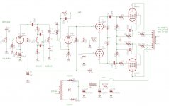
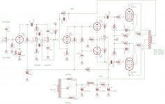
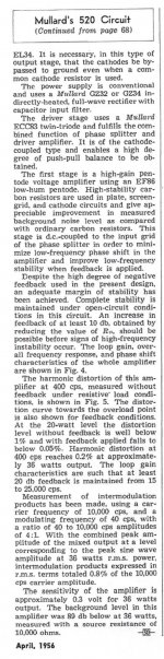
hello to all! what do you think about this circuit desing?
hifi UL stereo amp 25w
Its simply a Mullard 5-20 with a lossy tone control stuck on the front end.🙂
Attachments

- Home
- Amplifiers
- Tubes / Valves
- 6SN7 6L6 DIY Tube Amp