Hi
I have embark on a making 6SL7 preamp using the attached schematic. When the power is on the tube will light up and all seems normal. The entire circuit will trip once the ground of the input is applied to the Ground copper bus. All other ground is via the Ground copper bus except for the heater cct. Kindly advise where did I went wrong?😕
Any comments or suggestion to the circuit will be most appreciated.
Thank you in advance
Attachments
Check your layout. The schematic will work, albeit, too much smoothing and 220v at 4.55A is a bit excessive!
Quite unclear from the diagram what your grounding arrangements are.
The PSU has far too much resistance, which can lead to subsonic problems. Fortunately you only have one stage so you should get away with it.
Difficult to think of an audio purpose for a 'preamp' with so much gain.
The PSU has far too much resistance, which can lead to subsonic problems. Fortunately you only have one stage so you should get away with it.
Difficult to think of an audio purpose for a 'preamp' with so much gain.
Check your layout. The schematic will work, albeit, too much smoothing and 220v at 4.55A is a bit excessive!
HI, JonSnell,
Will too much current will cause a trip?
Thanks
Quite unclear from the diagram what your grounding arrangements are.
The PSU has far too much resistance, which can lead to subsonic problems. Fortunately you only have one stage so you should get away with it.
Difficult to think of an audio purpose for a 'preamp' with so much gain.
Hi DF96,
Attached a clearer schematic, hope that you can advise. I have also considered the grounding the copper ground bus to the "earth" via 0.22uF X2 type in parallel with a 100ohm resistor.
Should I ground the the heater's PSU ground to earth ground too?
Thank you for your advice and recommendations
Hi DF69,
The preamp is meant to drive a KT88. too much gain?
Attachments
Can you explain what 'Trip' means please?
For example ''trips mains circuit breaker'' / ''trips power amp protection'', etc.
Any good clear pictures?
For example ''trips mains circuit breaker'' / ''trips power amp protection'', etc.
Any good clear pictures?
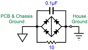
John Broskie suggests the following for linking circuit ground and earth.I have also considered the grounding the copper ground bus to the "earth" via 0.22uF X2 type in parallel with a 100ohm resistor.
Should I ground the the heater's PSU ground to earth ground too?
You don't need anywhere near 4.5A from your transformer. The circuit will only require about 2ma per channel. You're using a 1000VA transformer for a <10VA load...
I Also agree with DF96. The large resistances make in the PS make for a very high Zout from it.
Last edited:
Can you explain what 'Trip' means please?
For example ''trips mains circuit breaker'' / ''trips power amp protection'', etc.
Any good clear pictures?
Hi Alan4411
Apologies for unclear explanation, trip meant tripping the main circuit breaker.
Thanks
Hi all,
Thanks for all inputs.
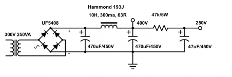
Is there any "workable" model/ schematic I can use for the PSU?
The PSU should be able to power up a KT88 SE with the 6SL7 as preamp / driver.
I am building the SE amp stage by stage. PSU and the 6SL7 stage being the first.
Thank you
hschaser ''trip meant tripping the main circuit breaker''.
Then take care as you have a Safety Issue.
I assume the 'Input socket' is an RCA type AND there is nothing plugged into it. In which case the outer ring should not be connected to anything (isolated from the chassis). Installing the 'red' wire should put the ring at the same potential as the green bus plane. (It should be just the same as connecting the red wire to an RCA socket ring 'in free space'. It is at the end of a wire and does not make a circuit.)
If you have a trip when connecting the red wire, I suspect the RCA ring is at a mains voltage or the green bus is... due to mis-connection or leakage.
Make sure the chassis is bonded to your safety earth and check for AC voltages from ground to the socket and bus before anything else.
The connections shown to the 'copper ground bus' appear to be in random order, so once you resolve the safety issue you may get hum. The PSU ground should be at the output of the PSU, not halfway along.
The situation you describe is impossible (mains breaker tripping when an internal ground is connected), therefore you have not built what you think you have built and told us you have built.
Is the transformer a proper power transformer, providing isolation (as shown in the diagram), or is it some sort of autotransformer? The high current rating is a hint towards the latter.
I now understand that this is not a preamp (and not a driver either) but actually the voltage amplifer stage of a power amp. Maybe you could ask the Mods to change the thread title?
Take extreme caution until you fix this. Looks like you might have 220V running all over the place. I have a feeling your Copper Ground Bus is actually a 220V high tension bus. Use caution and take a measurement of the copper ground bus verse the house ground (Make sure you are insulated in the process). From there unplug and use an ohm meter to go backward and sort out what went wrong.
Hi, I see at least one issue. The actual active portion of the circuit will work fine. I use similar ones all the time. The grounding of the heater supply as shown will eventually cause failure of the tubes from heater to cathode arcing. The spec for new tubes is typically 200 volts between any part of the heaters and any of the cathodes. With 250 on the upper anode the usual operating voltage at the middle cathode will be about 1/2 that or 125. It would seem to be fine.....however I have found with age the value deteriorates and 125 can cause failures. I have had that occur with 6SL7s. Also during warm up the B+ may be much higher and one side or the other of the tube can warm up faster. It only takes a second or two for arcing to occur. A common way to keep this from happening is to float the heater circuit and attach a positive voltage (about 1/4 to 1/3 of the upper anode one) to the heaters. This would be through a relatively high resistance value divider. I typically use something like 200K for the hot end and 68K for the cold end resistors. The junction would go to the heater circuit. A capacitor connected to the junction going to the ground of about 1-2 uf preferably a poly type will help reduce noise in the circuit as well.
Now the main problem...I agree that something probably dangerous is the cause of the tripping. Many things come to mind, bad transformer, a wiring error, and possibly even (I have had this happen) a wiring error in the mains supply from the wall.
Now the main problem...I agree that something probably dangerous is the cause of the tripping. Many things come to mind, bad transformer, a wiring error, and possibly even (I have had this happen) a wiring error in the mains supply from the wall.
The connections shown to the 'copper ground bus' appear to be in random order, so once you resolve the safety issue you may get hum. The PSU ground should be at the output of the PSU, not halfway along.
The situation you describe is impossible (mains breaker tripping when an internal ground is connected), therefore you have not built what you think you have built and told us you have built.
Is the transformer a proper power transformer, providing isolation (as shown in the diagram), or is it some sort of autotransformer? The high current rating is a hint towards the latter.
I now understand that this is not a preamp (and not a driver either) but actually the voltage amplifer stage of a power amp. Maybe you could ask the Mods to change the thread title?
Hi DF96,
Is there a proper way / order of grounding? Pls enlighten me if yes.
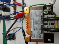
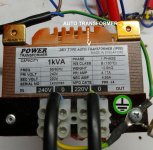
The transformer is definitely a proper power transformer (pls see attached pic) but with a high amp rating.
Pls forgive me for an ignorant question, are there differences in a preamp, Driver and voltage amplifier? what i intend to do is to take the output from a 6SL7 to drive a KT88 (used 6SL7 as it is of higher gain to drive KT88)
Thank you once again for your precious insight.
Attachments
Take extreme caution until you fix this. Looks like you might have 220V running all over the place. I have a feeling your Copper Ground Bus is actually a 220V high tension bus. Use caution and take a measurement of the copper ground bus verse the house ground (Make sure you are insulated in the process). From there unplug and use an ohm meter to go backward and sort out what went wrong.
Hi Alllensoncanon,
Thank you and will sure do insulate myself.
You should tell us what you are trying to achieve. Are you really wanting to build a KT88 amp with a 6SL7 input / driver stage? Are you trying to build a 6SL7 preamp in 1 enclosure to drive a KT88 output stage in another enclosure? You are destined to have issues if you don't spell things out.
Hi Leadbelly,
I am wanting to build a SE KT88 amp with a 6SL7 input / driver stage.
Apologies for the unclear explanations.
I am wanting to build a SE KT88 amp with a 6SL7 input / driver stage.
Apologies for the unclear explanations.
The transformer is definitely a proper power transformer (pls see attached pic) but with a high amp rating.
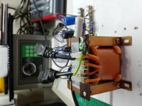
Err, no it is not.
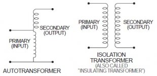
It HAS TO BE an 'Isolating Transformer'. That is Two separate windings with No connection between them. So mains cannot get onto your power supply circuits.
That is an 'Auto Transformer', it actually says so on the label, a tapped single winding. That connects the mains voltage directly to your power supply, and eventually, you, your family and pets. Dangerous - Do Not use it...
Please get a proper isolating transformer before continuing.
Your 'trip' has worked fortunately and already saved you from harm. As others say there are issues with the grounding layout generally, but after you change that transformer...
Attachments
Last edited:
Err, no it is not.
It HAS TO BE an 'Isolating Transformer'. That is Two separate windings with No connection between them. So mains cannot get onto your power supply circuits.
That is an 'Auto Transformer', it actually says so on the label, a tapped single winding. That connects the mains voltage directly to your power supply, and eventually, you, your family and pets. Dangerous - Do Not use it...
Please get a proper isolating transformer before continuing.
Your 'trip' has worked fortunately and already saved you from harm. As others say there are issues with the grounding layout generally, but after you change that transformer...
Very much thanks for point out the print!!!
Am very glad that I came out unharmed!!!!!

Most appreciated!!!!!🙂🙂
Will get a proper one...
How can I test for an isolating transformer or an autotransformer if there is no marking on them?
Thanks once again!!!!
How can I test for an isolating transformer or an auto transformer if there is no marking on them?
Easy if you have a multi-meter.
Select either the 200 or 2K Ohms range. Make sure the transformer is not connected to anything of course and clip one meter lead to any lead/tag on the transformer, then touch each of the other leads/tags in turn.
- If it is an Auto Transformer, every lead will give a resistance reading.
- If it is an Isolating Transformer, only one or two of the leads give a resistance reading, but all the others will read 'Open Circuit'.
Go and test the low voltage one you have and see.
This might help.
Attachments
- Status
- Not open for further replies.
- Home
- Amplifiers
- Tubes / Valves
- 6SL7 pre-amp (driver)