6sc7 shared cathode guitar preamp questions
Thanks in part to help from this forum, I've built or repaired about a dozen guitar amps over the past year. Finally hit a new one that has left me with some questions.
I bought a cheap, broken UPX-003a phono preamp thinking I'd turn it into a guitar preamp to get some of my smaller amps into high gain distortion. It uses a 6sc7 shared cathode dual triode, which I found was used in the Fender 5c2 Princeton, so I based my design on the 5c2 preamp (up through the volume pot but not including the tone control so far). The only significant difference is my power supply provides only 170V, so thus far I'm sticking with the original 68k and 47k plate resistors from the UPX-003a instead of the 250k resistors from the 5c2 — may adjust those values later, but for now I figure these will work.
So far so good, I have a little 5c2-ish preamp driving my Champ into glorious tube overdrive. Now for the questions:
1) Despite the relatively tame (compared to 12ax7) triodes running at lowish plate voltage, this thing produces a lot of gain! Is there any reason to worry about the signal level going into my amps? How much AC voltage can a 12ax7 grid handle?
2) The 5c2 has a fixed 250k / 75k voltage divider between the two 6sc7 stages. I thought I'd give myself a gain control, and installed a 500k pot there instead. But, if I turn that pot up beyond about 25%, the preamp goes into some kind of wild oscillation and starts producing periodic chirping noises. I'm guessing this has to do with the shared cathode, though it is bypassed. But I'm not sure how to think about how that works. Any ideas about what might be going on, or how to diagnose?
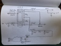
I'm attaching a quick drawing of exactly what I have.
Thanks in part to help from this forum, I've built or repaired about a dozen guitar amps over the past year. Finally hit a new one that has left me with some questions.
I bought a cheap, broken UPX-003a phono preamp thinking I'd turn it into a guitar preamp to get some of my smaller amps into high gain distortion. It uses a 6sc7 shared cathode dual triode, which I found was used in the Fender 5c2 Princeton, so I based my design on the 5c2 preamp (up through the volume pot but not including the tone control so far). The only significant difference is my power supply provides only 170V, so thus far I'm sticking with the original 68k and 47k plate resistors from the UPX-003a instead of the 250k resistors from the 5c2 — may adjust those values later, but for now I figure these will work.
So far so good, I have a little 5c2-ish preamp driving my Champ into glorious tube overdrive. Now for the questions:
1) Despite the relatively tame (compared to 12ax7) triodes running at lowish plate voltage, this thing produces a lot of gain! Is there any reason to worry about the signal level going into my amps? How much AC voltage can a 12ax7 grid handle?
2) The 5c2 has a fixed 250k / 75k voltage divider between the two 6sc7 stages. I thought I'd give myself a gain control, and installed a 500k pot there instead. But, if I turn that pot up beyond about 25%, the preamp goes into some kind of wild oscillation and starts producing periodic chirping noises. I'm guessing this has to do with the shared cathode, though it is bypassed. But I'm not sure how to think about how that works. Any ideas about what might be going on, or how to diagnose?
I'm attaching a quick drawing of exactly what I have.
Attachments
Last edited:
> two 6sc7 stages. ........ some kind of wild oscillation and starts producing periodic chirping noises.
It is too late tonite to re-draw to show the action. Two cascaded stages on a common cathode resistor makes positive feedback, a multivibrator, an oscillator. The period relates to the interstage C-R network and the common cathode cap.
The Fisher (or here GE) phono did not use a cathode R and C, am I right? Hard grounded. No positive feedback. Good for signal levels lower than guitar pickup (mag phono).
You are running this into the instrument input of a Champ?? How gain-hungry are you?? That's a gain of maybe a thousand. A Champ is Almost Enough. 1,000X more is Way TOO Much! Even going direct to a 6V6 you don't often need THAT much gain. Leo fixed both issues with the interstage divider. You could do that, and also a pot for further turn-down, because 4 stages (two in UPX-003a, two in Champ) is insane even with a 4:1 divider.
If you really want disTORTion, what you want is a cascade of gain and loss. Study the classic many-tube headbanger amps.
As long as you have several-many-K of resistance in series with the Champ's input grid, just turn it up until it craps-out (grid-blocks) and turn it back a scooch. 12AX7 grid in g-amp can easily stand 10mA half the time. A 34k series resistor means 340 Volt peaks into the grid. You are not near in danger of that. However it is about a hundred times more than it takes to slap a 12AX7 senseless.
Yes, original UPX-003a had the cathode lug soldered directly to a nearby ground lug. And now the chirping starts to make sense: I thought about the potential for feedback between the stages, but figured it shouldn't be an issue with the cathode resistor bypassed. Now I realize it's bypassed at audio frequencies — and chirps were happening maybe a couple times a second. I suppose I was hearing AF harmonics of an ~2Hz square wave LFO. I hadn't intended to make an analog synthesizer!
An aside on feedback & oscillation in case anyone reading along needs to work it out like I did: 1st stage inverts the signal, so 2nd grid moves opposite to the 1st. Cathode voltage follows the 2nd grid (more than the 1st grid, because gain). So, if 1st grid goes a bit high, that means lower cathode voltage, which makes the 1st grid relatively even higher, feeding back until the 2nd stage reaches cutoff. Then the slightest downward twitch of the 1st grid drives the cycle in the other direction.
I've mostly been enjoying this with its output volume set quite low, and I'm now getting the concept of clipping and attenuating at each stage. But, I could stand to hear a little more clipping between stages. With output volume set near unity, the maximum inter-stage distortion (before it starts oscillating) is mild.
I guess the inter-stage voltage divider attenuates the feedback enough to prevent oscillation? Maybe a smaller inter-stage cap would have a similar effect while letting the audio frequencies get a bit louder. And I suppose a larger bypass cap would also help drive oscillations down toward a frequency that the inter-stage RC filter attenuates sufficiently.
I tried strapping on a second cathode bypass cap in parallel, and as I guessed, the extra capacitance lets me turn up my gain pot further and get the second stage into a nice overdrive without getting the LFO going. Any reason I should worry about making the a cathode bypass cap too big (other than, I guess, time to establish bias on startup)?
High-uFd low-Volt e-caps used to be not-cheap and dubious life.
Here, a small drop of original C is not a drop of gain but (as you know) a loud howl/putt.
Today a 2,200uFd 5V costs pennies and lasts decades. Even when 90% of its uFd are gone it will work OK. Do it.
Here, a small drop of original C is not a drop of gain but (as you know) a loud howl/putt.
Today a 2,200uFd 5V costs pennies and lasts decades. Even when 90% of its uFd are gone it will work OK. Do it.
This is working and sounding great now with a 470uF 16V cathode bypass cap and some voltage dividers to keep the max gain from each stage within reason (though just barely). Thanks for your help!
As I started to bolt things in place and button it up, another question presented itself: the original UPX-003a phono preamp doesn't include a fuse. My rule of thumb thus far has been to put an appropriately-chosen fuse in any power supply I build (so, excluding things that use wall-warts), but this is the first time I've worked on anything that doesn't match my rule. How should I think about whether I need to add one here?
As I started to bolt things in place and button it up, another question presented itself: the original UPX-003a phono preamp doesn't include a fuse. My rule of thumb thus far has been to put an appropriately-chosen fuse in any power supply I build (so, excluding things that use wall-warts), but this is the first time I've worked on anything that doesn't match my rule. How should I think about whether I need to add one here?
An interesting thought!...Would using an LED instead of RC bias work for a common cathode tube?
I think there are two issues to consider: firstly, the LED needs to cope with the biggest peak currents the tubes are capable of, without burning out. This shouldn't be an issue with the low currents a 6SC7 is capable of.
Secondly, a forward-biased LED still has a non-zero dynamic resistance. I think that dynamic resistance is much bigger than a regular rectifier diode, too.
That means you'd still get the annoying unwanted coupling between the two cathode currents of the 6SC7, so you'd probably still have to put a big whopping decoupling capacitor in parallel with the LED.
So I suspect that perhaps there wouldn't be much of an advantage in using an LED for a 6SC7.
-Gnobuddy
Thanks. I thought that would be the case. I have a stash of 6J6 tubes (7 pin dual triodes with common cathode) which I have been using for phase inverters. Might try them in a preamp next - just cos I have them.
A thought: these days it isn't hard to generate a small negative bias voltage using an inexpensive DC-DC converter....6J6 tubes (7 pin dual triodes with common cathode)...
Using one of these would allow you to tie the shared 6J6 cathodes to ground, eliminating unwanted coupling between them. The control grids would be biased negative through the usual 1Meg or similar resistor, using your negative bias voltage. Ta-da, you have the best of both worlds...the bias point you want, without unwanted interaction, from inexpensive and unloved valves you already have! 🙂
One possibility is to simply run your heaters from a 6 V switching power supply, wired with its positive output to ground, so that you also have up to (-6V of DC bias voltage available.
Another possibility is to use something like this nifty module ( RAC10-15DK/277 Recom Power | Power Supplies - Board Mount | DigiKey ), which will run on AC or DC input (up to 305 V AC, up to 430 V DC), and spit out +/-15 volts you can use as you see fit.
That little module costs $16 in Canada and $11 in the USA. Perhaps it is still affordable in New Zealand?
And there is also another option: a 3V lithium coin cell could provide you negative grid bias voltage for years, since there is virtually no current draw involved. The only catch is that you have to remember to replace the cell before its output drops to zero and the valves overheat and fail!
Finally, in the untried-but-it-should-work category, there are shunt regulator chips like the TL431. It has a 0.2 ohm output impedance, can comfortably sink currents up to tens of mA (100 mA maximum), and can be set to provide a regulated voltage anywhere between 2.5V and 36V. Use one of these in place of a shared cathode resistor, and you should be able to dial in any bias voltage the 6J6 is likely to want, with negligible unwanted signal interaction. (But it's an untried idea, and there is always the possibility that it won't work as envisioned.)
-Gnobuddy
Thanks Gnobuddy. That is just the sort of information I look for on this forum to get my thinking out of its box. Much appreciated.
- Home
- Live Sound
- Instruments and Amps
- 6sc7 shared cathode guitar preamp