Hello felllow audio DIY-ers!
I'm just starting to build a 25 year old project...a stereo push pull tube amplifier I "started" to build when I was in highschool...but never got to finish....I guess it's about time 🙂
Back then there was no chance to get a good output transformer...for me anyway..and the internet was not what it is today...some had dialup I didn't...so I gathered the chunkiest transformers I could find planning to open them up and rewind them, all local magazines with tube amplifier articles...found old electronic engineers in my town to source schematics datasheets and..the tubes of course. Things stopped when I tried to open up and rewind the output transformers ...good luck with that!..and highschool finished priorities changed...
I the meantime I occasionally "light up" about tube amps or other things while browsing the internet so at some point I purchased toroidal output transformers, all components for a linear regulator and an old grundig tv set transformer
So having basically all components sitting for the amplifier...I got this "urge" a few days ago to build it and I started putting together a chassis with all the components.
I don't know what's gotten into me I'm not even into tube amps anymore...or am I? I find myself salivating when I see nice tube amps or full boxes of interesting NOS tubes and wish to have them 🙂
I'll post some pictures and later I'll have some questions for sure...
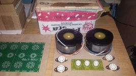
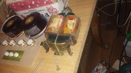
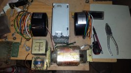
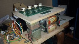
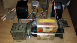
This are the transformers sockets and pcb's trying to make a layout...I'll be using the small yellow pcb for now...the green one is nicer but I have chassis mount sockets and I will not buy other components until I build something, later I will replace/make another pcb...I have boxes of components for all sorts of projects sitting just like this one...because..well "I need other pcb mount tube sockets...or I need to buy something"
Attachments

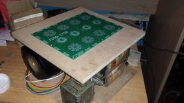
I had these two square MDF plates 25x25cm...they were for something else but I will use them for the current iteration of the chassis.
I have another unfinished 12 year project just like this one...a nice CNC machine 99% all components sitting there unmounted...I guess It's about time for that too 😀 ...as soon as it will be done and I figure out LinuxCNC I will make a proper enclosure for the amp....maybe put an SMPS supply instead of that bulky transformer, I saw some SMPS PS's on aliexpress I don't know how good they are but there is one that looks promising.
The transformer is 220v in 220v out and another two 10v windings so I will use a voltage doubling rectifier and I also plan to regulate the filaments supply and bias of course. For the bias supply I have another small transformer about 60vac
Attachments
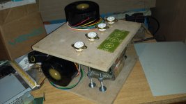
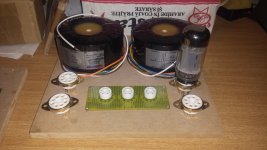
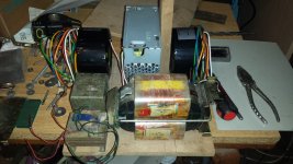
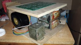
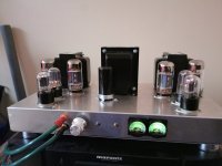
I pondered a little about the chassis and transformers placing after I first mounted the power transformer...first plan was to put the power transformer in the front below and the output transformer on the top plate in the back to put as much distance as possible between them, but the space for tubes was getting tight and there was a lot of unused space below the top plate, so I moved all transformers in what will be the amplifier body, with all the tubes sitting on top
Attachments

Looks like you have the parts for a nice 6P3S-E PP amplifier. Can’t quite make out which Toroidy output transformers you got, but presumably they are those with 6.6 k primaries. Toroidy’s can make beautiful music. What schematic design are you building?
Welcome to tube land and good luck with your project.
Welcome to tube land and good luck with your project.
Hello! I heard and read good reviews about Toroidy OPT, so I think you should be fine with them.
If you don’t mind, I have a suggestion for your build.
I would not regulate the Neg Bias voltage.
The reason being is, if the mains voltage goes up, your B+ goes up as well. But in the same time your Neg Bias stays the same. As a result, your power valves will run hotter.
To be honest, I think that a better approach will be not to use regulated Neg Bias. In this case when the mains voltage goes up, your bias voltage will go up as well and that keeps you on the safe side.
On the other hand if you are willing to regulate the neg bias voltage only to achieve better ripple rejection, then maybe you can use a cap multiplier instead.
Good luck with your build!
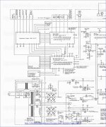
I agree with @KDMAudio re. regulation of the bias. A better approach is “Extended Flexible Bias” (EFB tm) by Dave Gillespie.
EFB modulates your bias voltage, as well as your screen supply according to the variation in B+ Kevin Ward adapted EFT to a 1625 PP amplifier which is close to your 6P3S-E tube, but with top cap.
EFB modulates your bias voltage, as well as your screen supply according to the variation in B+ Kevin Ward adapted EFT to a 1625 PP amplifier which is close to your 6P3S-E tube, but with top cap.
Attachments
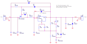
Regarding the power supply I have an LT3080 for a regulator I found here on diyaudio "the 21st century maida regulator" a floating regulator design...that's what I'm planning to use. I gutted a SFX PC power supply to house the high voltage components. I am kind of "afraid" of going unregulated...I have read some here and there about proper wiring and grounding needed with a "classic" tube amp design with non regulated power supply and I don't want to have to deal with all that. Also I will have about 610V after rectification with a voltage doubler and I have to drop that to below 500V...from what I've been reading about this tubes they can take 500V and maybe above
So regarding the bias supply..if the B+ is regulated than the bias should be regulated too. I have read some things about leaving the bias unregulated but that was for unregulated B+...so from what I understood either you regulate all supplies or leave all unregulated.
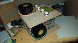
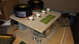
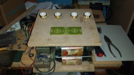
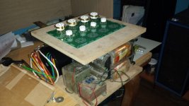
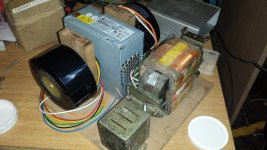
This is how I have set up the transformers, OT's are the 6.6k "EL34PP" ones from Toroidy, and in the front placed all power supply transformers...there will be 3 like in the in the last picture: the big one for B+ and filaments and the two small ones one has the 60vac for bias ant the other has two 20v windings suspended from the top plate...this will be used for a dual voltage supply, I plan to experiment with using an opamp for the forst stage/phase splitter, I have an OPA4228 and I have read some good things about using opamps for phase splitter/frst stage.
How I'm thinking about this amp...make it a sort of "testbed amp" with adjustable supply, and in the end with that green prototype pcb that has 8 octal sockets and 4 noval and some other small type in between...4 of the octals are for the power tubes, the small sokets for pre valves and the other 4 octal are also for "pre" tubes like 6SL7 wich I also read good things about their sound....or the the russian version. But in the first iteration I will mount the sockets I have directly on the top plate with spacers and use the small 3 noval sockets PCB. That's because my octal sockets are chassis mount...I will get PCB sockets later. I kind of want to leave it "open ended" I see many interesting configurations...maybe I want to see what is the difference in how they sound...
I have not decided upon a schematic yet I am researching about this and drawing schematics by hand, taking parts I need out of them, I will post some of the "starting point" schematics I have saved for power supply..and amplifier, but the first thing I wat to do is the power supply.
I also have some schematics from "back in time" old local magazines, I will post them ...not that I plan to use them but they are useful they contain clear explanations about how everything works...romanian only...and a hungarian one. This one more for nostalgia...I have to take some time to take photos of them.
So regarding the bias supply..if the B+ is regulated than the bias should be regulated too. I have read some things about leaving the bias unregulated but that was for unregulated B+...so from what I understood either you regulate all supplies or leave all unregulated.
This is how I have set up the transformers, OT's are the 6.6k "EL34PP" ones from Toroidy, and in the front placed all power supply transformers...there will be 3 like in the in the last picture: the big one for B+ and filaments and the two small ones one has the 60vac for bias ant the other has two 20v windings suspended from the top plate...this will be used for a dual voltage supply, I plan to experiment with using an opamp for the forst stage/phase splitter, I have an OPA4228 and I have read some good things about using opamps for phase splitter/frst stage.
How I'm thinking about this amp...make it a sort of "testbed amp" with adjustable supply, and in the end with that green prototype pcb that has 8 octal sockets and 4 noval and some other small type in between...4 of the octals are for the power tubes, the small sokets for pre valves and the other 4 octal are also for "pre" tubes like 6SL7 wich I also read good things about their sound....or the the russian version. But in the first iteration I will mount the sockets I have directly on the top plate with spacers and use the small 3 noval sockets PCB. That's because my octal sockets are chassis mount...I will get PCB sockets later. I kind of want to leave it "open ended" I see many interesting configurations...maybe I want to see what is the difference in how they sound...
I have not decided upon a schematic yet I am researching about this and drawing schematics by hand, taking parts I need out of them, I will post some of the "starting point" schematics I have saved for power supply..and amplifier, but the first thing I wat to do is the power supply.
I also have some schematics from "back in time" old local magazines, I will post them ...not that I plan to use them but they are useful they contain clear explanations about how everything works...romanian only...and a hungarian one. This one more for nostalgia...I have to take some time to take photos of them.
Attachments

Last edited:
Having all voltages regulated is a good option too, of course. Please consider that the classic LM317 has better PSRR than the LT3080. There are also several designs based on Maida type regulator with the 317 chip, including an example in their datasheet.
Regards,
Mircea
Regards,
Mircea
Yes but I already have the LT3080. I have a habit of ordering components for all sorts of projects..then leaving them unused. Like lots of 100uF 400v caps...they were for a welding inverter/high current source...I was crazy enough to plan such a thing...research it...order 120 euro worth of components...actually it's a good thing I didn't build it I'm sure it saved myself lots of time and frustrations. So now I will make use of what I have.
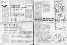
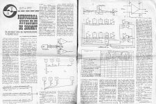
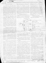
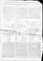
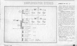
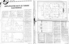
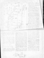
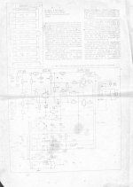
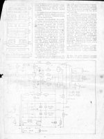
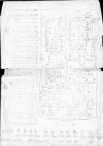
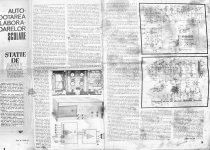
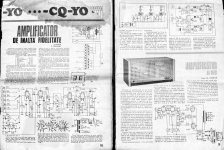
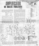
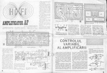
I took some pictures of the old schematics and articles about amplifiers, grounding, noise, power supply...these ones not so old actually some were published in the 90's by an engineer that was publishing really interesting schematics at the time..some higher performance ones. They are in Romanian ...so only useful for those who understand them. The hybrid amplifier was catching my attention at the time.
I took some pictures of the old schematics and articles about amplifiers, grounding, noise, power supply...these ones not so old actually some were published in the 90's by an engineer that was publishing really interesting schematics at the time..some higher performance ones. They are in Romanian ...so only useful for those who understand them. The hybrid amplifier was catching my attention at the time.
Attachments
-
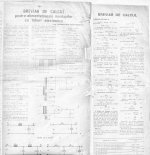 Calcul Transformatoare Alimentare Tuburi.JPG815.7 KB · Views: 109
 -
 Verificarea Amplificatoarelor.JPG736.2 KB · Views: 90
 -
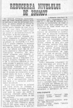 Reducerea Zgomotului 2-2.JPG343.4 KB · Views: 94
 -
 Reducerea Zgomotului 1-2.JPG786.5 KB · Views: 97
 -
 AMP 3 hybrid Tehnium 2 98 A Mateescu 2-2.JPG607.9 KB · Views: 105
 -
 AMP 3 hybrid Tehnium 2 98 A Mateescu 1-2.JPG690.5 KB · Views: 136
 -
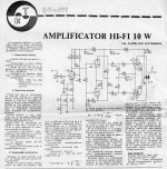 AMP 2 10w Tehnium 4 1990 A Matescu.JPG974.8 KB · Views: 189
 -
 AMP 1 Tehnium 11 1989 A Mateescu. 2-2.JPG427.6 KB · Views: 125
 -
 AMP 1 Tehnium 11 1989 A Mateescu. 1-2.JPG629.4 KB · Views: 120
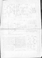
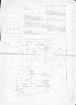
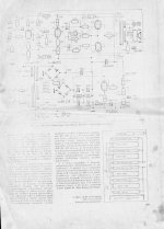
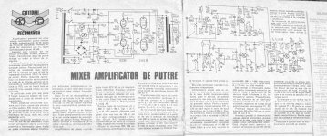
And here are some Hungarian schematics I scored at the time. Again...only useful for those who understand them. There are some interesting things there...from looking at the schematics... I don't understand the language so the order may be wrong. The original paper is a very pale xerox copy...if anyone is interested maybe I could try taking better pictures
I don't really plan to use these schematics...just posting them. I'm sorry I don't understand the text I'm sure the articles are informative..
I don't really plan to use these schematics...just posting them. I'm sorry I don't understand the text I'm sure the articles are informative..
Attachments
-
 Hungarian Amp 7 p111.JPG387.1 KB · Views: 102
 -
 Hungarian amp 6.JPG455.3 KB · Views: 91
 -
 Hungarian Amp 5.JPG321.5 KB · Views: 80
 -
 Hungarian amp 4.JPG352.7 KB · Views: 81
 -
 Hungarian Amp 3 p109.JPG451 KB · Views: 92
 -
 Hungarian Amp 3 p108.JPG486.6 KB · Views: 80
 -
 Hungarian Amp 2.JPG371.5 KB · Views: 87
 -
 Hungarian Amp 1.JPG390.7 KB · Views: 92
There are some "specs" there on the first "Hungarian Amp" hand written for 6P3C-E I don't know where I got those..seem totally wrong I remember I was not finding the tube in any catalog I could lay my hands on...so I noted that...probably another tube.. I don't remember where from...it's so good we have the internet today 😀
These are the older schematics...older than me 😀 These are like "vintage" tube amps from 70's
Not planning to use of course.
Not planning to use of course.
Attachments
These days keep ending up in places like this when I am looking for schematics or reading about tubes:
https://www.tubecad.com/2014/08/22/Partial-Feedback Hybrid Amplifier.png
https://diyaudioprojects.com/Tubes/KT88-Push-Pull-Tube-Amp/
https://www.tubecad.com/2014/08/22/Partial-Feedback Hybrid Amplifier.png
https://diyaudioprojects.com/Tubes/KT88-Push-Pull-Tube-Amp/
You maybe want to include these, three different type of amplifiers, all very well regarded :
Attachments

Eico HF-89, whole user manual including build and schematic. Uses EL34, but very easy convert to 6P3S-E
1) Reduce B+ to 400~415V. Hammond 372jx with silicon rectifiers will do the job.
2) - 40V bias, ~ 40mA quiescent current for the output tubes.
3) 6.6K UL output transformer, 30+ watts, like Hammond 1650HA.
1) Reduce B+ to 400~415V. Hammond 372jx with silicon rectifiers will do the job.
2) - 40V bias, ~ 40mA quiescent current for the output tubes.
3) 6.6K UL output transformer, 30+ watts, like Hammond 1650HA.
Attachments
Thanks! Actually I was just looking at some Harman Kardon Citation clone pcb's recently...now I won't use pcb clones for this amp but I can test different schematics on the prototype pcb's. My plan is to make this as a configurable amp for myself to play with it but after everything works I will make another "proper" chassis...metal, no mdf, purchase a switching supply,I have 8 6P3S-E's, so I move the OT's to that chassis and sell it to a friend.., than buy other OT's for my chassis...for this I will use some good clone pcb's, and it "feels" more "thrustworthy" for who ever will have it..it's a clone of a well known amp not something I cooked up...that might catch fire 😀
- Home
- Amplifiers
- Tubes / Valves
- 6P3S-E push pull amp build log