Hi,
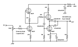
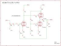
I've started a 6n6p white cathode follower build, wanted it to be a combo buffer/line/headphone stage switching between each. I was basing on Kodabmx's 6n6p wcf headphone stage and a similar headphone stage from moses1202, but omitted the first gain stage as I don't need any gain.
I've made a muchedumbre xl using 6ns7 before, and a couple of Frank's 6sn7 line stage (without regulator) fancied using the OD3 PSU as I had the parts and wanted to try a gas tube.'
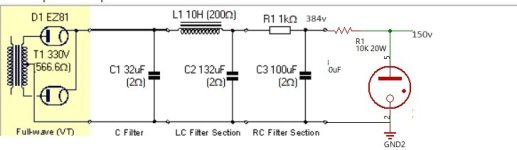
I wanted this to be a parts bin job, so used what I have which meant only one choke for the PSU and swapped the second choke for an RC section. I also dropped the 150uf c4 as I read gas tubes will oscillate with more than .1uf on the output. The plan was to see how much current the 6n6p's drew and then tweak the RC dropping resistor and OD3 series resistor and cathode resitor values until I was happy. I've only got a 5w 10k, so was just going to get things working in test then buy a higher wattage, or use some parallel resistors on hand. and also get a small cap < .1uf cap to reduce noise.
The PSU section all works and I get 150v from the OD3 - without the 6n6p load the B+ is about 340v and the OD3 gives 150v. I've wired using the jumper pins so I can remove the OD3 and the B+ is cut, works well.
I've just wired up the buffer input and output to save doing all of the input and headphone cabling, using some .68uf which are fine for my 100k input.
The WCF section is not giving out the voltages I expect. With 150v on the 270 ohm plate resistors I'm only getting 10v at the first triode cathode/second triodes plate, so the 100ohm second triode cathode resistors is seeing mv's where I thought I should see half of b+ so ~75v. I've checked my wiring and compared to my 6ns7 wcf and looks right, but must be a mistake somewhere. The B+ with the 6n6p's loaded is still around 340v.
I wired up without the OD3, so ~380V plate, and got 20v at the cathode/plate output junction and about 4ma through the 6n6p's. I've swapped the grid stoppers between 10k and 300ohm, didn't expect a difference and got none.
I've tried 3 sets of 6n6p and 2 different ez81's. No difference.
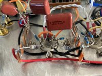
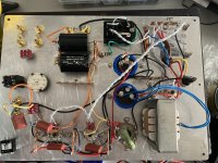
I've included the kodabmx and moses1202 schematics, a version with my values and my psu, plus pics of the build. Hoping someone can tell me what I've done wrong 🙂
Once I know what's up I'm going to strip and rewire the WCF section as I should have rotated the 9pin sockets to keep the heater wiring at the back.
ta
Rob
I've started a 6n6p white cathode follower build, wanted it to be a combo buffer/line/headphone stage switching between each. I was basing on Kodabmx's 6n6p wcf headphone stage and a similar headphone stage from moses1202, but omitted the first gain stage as I don't need any gain.
I've made a muchedumbre xl using 6ns7 before, and a couple of Frank's 6sn7 line stage (without regulator) fancied using the OD3 PSU as I had the parts and wanted to try a gas tube.'
I wanted this to be a parts bin job, so used what I have which meant only one choke for the PSU and swapped the second choke for an RC section. I also dropped the 150uf c4 as I read gas tubes will oscillate with more than .1uf on the output. The plan was to see how much current the 6n6p's drew and then tweak the RC dropping resistor and OD3 series resistor and cathode resitor values until I was happy. I've only got a 5w 10k, so was just going to get things working in test then buy a higher wattage, or use some parallel resistors on hand. and also get a small cap < .1uf cap to reduce noise.
The PSU section all works and I get 150v from the OD3 - without the 6n6p load the B+ is about 340v and the OD3 gives 150v. I've wired using the jumper pins so I can remove the OD3 and the B+ is cut, works well.
I've just wired up the buffer input and output to save doing all of the input and headphone cabling, using some .68uf which are fine for my 100k input.
The WCF section is not giving out the voltages I expect. With 150v on the 270 ohm plate resistors I'm only getting 10v at the first triode cathode/second triodes plate, so the 100ohm second triode cathode resistors is seeing mv's where I thought I should see half of b+ so ~75v. I've checked my wiring and compared to my 6ns7 wcf and looks right, but must be a mistake somewhere. The B+ with the 6n6p's loaded is still around 340v.
I wired up without the OD3, so ~380V plate, and got 20v at the cathode/plate output junction and about 4ma through the 6n6p's. I've swapped the grid stoppers between 10k and 300ohm, didn't expect a difference and got none.
I've tried 3 sets of 6n6p and 2 different ez81's. No difference.
I've included the kodabmx and moses1202 schematics, a version with my values and my psu, plus pics of the build. Hoping someone can tell me what I've done wrong 🙂
Once I know what's up I'm going to strip and rewire the WCF section as I should have rotated the 9pin sockets to keep the heater wiring at the back.
ta
Rob
Attachments

Last edited:
You can't just omit the first stage as it provides the bias for the second stage. The grid of the top triode needs to be at ~70 V, add a resistor divider from B+.
Also the 150V supply is high impedance without decoupling. The gas tube should be used as a reference for a mosfet (or triode) pass element, instead of taking B+ direct from it.
Right, thanks. Is bias the job of the 1m resistor from B+ to the grid on the muchedumbre xl? Could have sworn I read that it was for something like balancing and could be omitted. But I might have just been high on solder, as I can't find it now.

Regarding the OD3 decoupling and PSU impedance. Would it help if I put a ~100uf decouping cap back in like moses1202 original PSU schematic?
Regarding the OD3 decoupling and PSU impedance. Would it help if I put a ~100uf decouping cap back in like moses1202 original PSU schematic?
The 100 uF would work (assuming it doesn't oscillate), so long as the current draw from the 6n6p's at all signal levels is low enough to keep some current flowing through the gas tube. Just need to monitor B+ while driving the headphones at high volume and check it stays at 150V.

sweet, thanks. Just tried 1m from the 150v, gave 58v, but stopped the gas tube from striking. will try a divider from before the gas tube and aim for 70v
If you ever try to simulate your LTSpice schematic, use "Meg" for megaohms, 1m is one milliohm (0.001) 🙂Hi,
I've started a 6n6p white cathode follower build, wanted it to be a combo buffer/line/headphone stage switching between each. I was basing on Kodabmx's 6n6p wcf headphone stage and a similar headphone stage from moses1202, but omitted the first gain stage as I don't need any gain.
I've made a muchedumbre xl using 6ns7 before, and a couple of Frank's 6sn7 line stage (without regulator) fancied using the OD3 PSU as I had the parts and wanted to try a gas tube.'
I wanted this to be a parts bin job, so used what I have which meant only one choke for the PSU and swapped the second choke for an RC section. I also dropped the 150uf c4 as I read gas tubes will oscillate with more than .1uf on the output. The plan was to see how much current the 6n6p's drew and then tweak the RC dropping resistor and OD3 series resistor and cathode resitor values until I was happy. I've only got a 5w 10k, so was just going to get things working in test then buy a higher wattage, or use some parallel resistors on hand. and also get a small cap < .1uf cap to reduce noise.
The PSU section all works and I get 150v from the OD3 - without the 6n6p load the B+ is about 340v and the OD3 gives 150v. I've wired using the jumper pins so I can remove the OD3 and the B+ is cut, works well.
I've just wired up the buffer input and output to save doing all of the input and headphone cabling, using some .68uf which are fine for my 100k input.
The WCF section is not giving out the voltages I expect. With 150v on the 270 ohm plate resistors I'm only getting 10v at the first triode cathode/second triodes plate, so the 100ohm second triode cathode resistors is seeing mv's where I thought I should see half of b+ so ~75v. I've checked my wiring and compared to my 6ns7 wcf and looks right, but must be a mistake somewhere. The B+ with the 6n6p's loaded is still around 340v.
I wired up without the OD3, so ~380V plate, and got 20v at the cathode/plate output junction and about 4ma through the 6n6p's. I've swapped the grid stoppers between 10k and 300ohm, didn't expect a difference and got none.
I've tried 3 sets of 6n6p and 2 different ez81's. No difference.
I've included the kodabmx and moses1202 schematics, a version with my values and my psu, plus pics of the build. Hoping someone can tell me what I've done wrong 🙂
Once I know what's up I'm going to strip and rewire the WCF section as I should have rotated the 9pin sockets to keep the heater wiring at the back.
ta
Rob
VR tube not lighting was just due to the tube not getting enough current. Reduced the series resistor, now at 2.6k, and have 270k bias resistors giving about 90v. Cathode at 2v on 100ohms, so about 20ma. B+ down to 277v, so about 6w through the vr series and I've got 2 6.5w in parallel, they are hot so will look for something like 20w, but all looking much better.
Thanks heaps @tikiroo 🙂
And I think I should start learning LTSpice sims, maybe save me having to resolder so much, thanks for the tip @jcalvarez
Think I'll strip this back and redo
Thanks heaps @tikiroo 🙂
And I think I should start learning LTSpice sims, maybe save me having to resolder so much, thanks for the tip @jcalvarez
Think I'll strip this back and redo
Everything back up and running. I did need to drop the series resistor value again (1.7k) to keep the VR tube lit when driving headphones to the max volume. But worked out well as I have just been paralleling to get values which gives me more combined wattage to handle the heat better.
The headphone section is low on gain, no surprise cos this is a buffer only! But I can get louder than I like with the volume at 8 or 9 out of 10 with 250 ohm headphones and a 2.5v DAC output.
The headphone was more of a “can I do this” rather than a must have.
Very happy with the sound out of all outputs though. Very clean, nothing lost and I’ve got the amp very quiet, so my best effort so far.
Great use of an old vintage NZ Beacon R02 transformer
Last edited:
Hello and forgive my bringing back this older thread.
Was looking at the values shown in the schematics for the WCF stage using 6N6P tubes.
I'm also interested in using them for driving low impedance cans (38Ω).
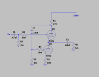
Right now, I'm using 6N23P in WCF configuration, with values as shown in Morgan Jones schematic below.
Only differences are bias in the first stage (R2=20000Ω, R3=470Ω) and R5 cathode resistor remains unbypassed.

So, for B+ of around 220VDC is it possible to just switch tubes (6N6P in place of 6N23P), without changing values for R4=120Ω and R5=270Ω (unbypassed)?
-Regarding R4 value, after reading the compiled article on WCF optimization, provided by Pearl Hi-Fi, I think 120Ω is closer to optimal than either 220Ω, 240Ω or 270Ω, seen in the schematics provided by the OP. That's according to my limited understanding, so I'm asking for kind advice on that.
-Regarding the (unbypassed in my case) cathode resistor value for R5=270Ω, I searched but couldn't find a method of calculating its optimal value.
From my limited understanding I assume it's not very critical for performance, but I see lower values 82Ω and 100Ω being used in the schematics provided by the OP.
Again, any advice on how to calculate its optimal value would be welcome.
Thanks in advance.
Was looking at the values shown in the schematics for the WCF stage using 6N6P tubes.
I'm also interested in using them for driving low impedance cans (38Ω).
Right now, I'm using 6N23P in WCF configuration, with values as shown in Morgan Jones schematic below.
Only differences are bias in the first stage (R2=20000Ω, R3=470Ω) and R5 cathode resistor remains unbypassed.
So, for B+ of around 220VDC is it possible to just switch tubes (6N6P in place of 6N23P), without changing values for R4=120Ω and R5=270Ω (unbypassed)?
-Regarding R4 value, after reading the compiled article on WCF optimization, provided by Pearl Hi-Fi, I think 120Ω is closer to optimal than either 220Ω, 240Ω or 270Ω, seen in the schematics provided by the OP. That's according to my limited understanding, so I'm asking for kind advice on that.
-Regarding the (unbypassed in my case) cathode resistor value for R5=270Ω, I searched but couldn't find a method of calculating its optimal value.
From my limited understanding I assume it's not very critical for performance, but I see lower values 82Ω and 100Ω being used in the schematics provided by the OP.
Again, any advice on how to calculate its optimal value would be welcome.
Thanks in advance.
- Home
- Amplifiers
- Tubes / Valves
- 6N6P WCF Help