Hello,
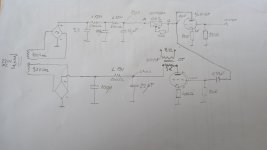
I'm for advice about 6N6P tube configuration loaded with CCS 10M45S as driver in SET amplifier with KT88 (triode mode). KT88 Q-point is Ua=390V, Ug=-40V, Ia=100mA and for driver 6N6P Ua=140V, Ug=-4V, Ia=20mA, B+=190V. Shematic and graph attached. I was expecting that driver will provide swing +/-40V plus +/-10V headroom, total +/- 50V = 100Vpp. After installation and power up measuremets for driver was a lot different than expected:
B+=188V, Ua=150V, Ia=20mA, Ug=-4V. Voltage drop on CCS is 188-154=34V
Problem is that I only have 60Vpp swing and after that is clipping. Output power only 10Vpp@8ohm = 1.2W. How to setup a Q-point with CCS that will be something like data on graph? Also I'm limited with power transformer source to 160Vac for dirver line B+. Can I use any other configuration without CCS to achive 100Vpp swing, except choke load? Maybe different driver tube? Or is it only solution to rewind this sec. winding to cca. 200Vac?
Attachments

Last edited:
You have only 34V on the CCS so that's the limit of excursion on pos swing.
You need to lower Va, one way to do is increase the tube bias current so Va drops, getting more headroom across the CCS.
Or increase B+ while keeping same tube bias current /Va, that will also increase headroom across CCS.
Jan
You need to lower Va, one way to do is increase the tube bias current so Va drops, getting more headroom across the CCS.
Or increase B+ while keeping same tube bias current /Va, that will also increase headroom across CCS.
Jan

How to calcuate current required for Ua=max 140V using CCS since CCS is dinamic resistance or how to calculate B+ required for qpoint 140V/20mA?
Reduce the 200R cathode bias resistor until you measure Ua = 140V.
Or until you get symmetrical clipping, indicating maximum swing. The only way to get more swing would be to raise Ua and/or reduce Ia.
Or until you get symmetrical clipping, indicating maximum swing. The only way to get more swing would be to raise Ua and/or reduce Ia.
Why such a low supply voltage anyway? I made the same mistake on a 6n6p headphone amp and got clipping when my mains voltage dropped at certain points of the day.
But you already have 350V in the unit.
You can R-C that down to anything you wish.
Jan
You can R-C that down to anything you wish.
Jan
Your original operating conditions on the 6n6p are perfect; a shame to compromise that when the fault is the C+ being too low.
I would steal your 400V B+ and go to the CCS, perhaps with a little filtering.
I would steal your 400V B+ and go to the CCS, perhaps with a little filtering.
As @zigzagflux wrote, use B+ and filtering to power CCS.
Sample:

p.s. you original 10M45S sketch is wrong, the gate/stopper/ resistor is missing.
Sample:
p.s. you original 10M45S sketch is wrong, the gate/stopper/ resistor is missing.
What is the purpose of R4 and D1?
I don't want to use 350Vac (500Vdc at 1st 10sec.) supply because caps in driver filter are rated 450V. I'll need to use zener diode and 10K to decrease this voltage to cca 250V.
I don't want to use 350Vac (500Vdc at 1st 10sec.) supply because caps in driver filter are rated 450V. I'll need to use zener diode and 10K to decrease this voltage to cca 250V.
Last edited:
Where does the 10k come from? Have you calculated how much current the stage draws, how much current the zeners need, and if 10k is the corrcect value for the drop?
Jan
Jan
Assuming your power transformer's 160VAC winding has sufficient current rating, why not use a full-wave voltage doubler on that secondary? That should give you about 300VDC B+ for the 6N6P. That way you could drop at least 50V across the 10M45S and it would work better. It would also stay within the 450V rating of your capacitors. But the 160VAC winding would have to have a high enough current rating for the task.

The total swing will be limited by the stage gain, and also be bounded by the bias voltage.
2 x bias voltage is the bound (peak + to peak -).
2 x bias voltage is the bound (peak + to peak -).
With a ccs plate load, stage gain will approach the triode's mu. Mu for the 6N6P is about 20, so let's say you get 18x gain.
The grid bias is -4V.
18*4 is 72V peak.
KT88 grid bias is -40V.
That means it will clip with about 40V peak signal applied.
I think that means at least 50V should be dropped across the 10M45S ccs. No?
The grid bias is -4V.
18*4 is 72V peak.
KT88 grid bias is -40V.
That means it will clip with about 40V peak signal applied.
I think that means at least 50V should be dropped across the 10M45S ccs. No?
rongon,
Correct.
If I remember the minimum voltage across the 10M45S (burden voltage) is 10 Volts. Below that it is not a current source.
Correct.
If I remember the minimum voltage across the 10M45S (burden voltage) is 10 Volts. Below that it is not a current source.
Looks like all good ideas so far. I like the doubler, or just using B+. But, if you don't want a doubler, or to use the other B+, then what about that first cap in the original C+ supply? It's only 3.3uf. If you're directly after a SS bridge you can take that way up, say 20 or 40uf, and get some more voltage right there. 210v is far better than 150v. I'd cool the idle just a little more myself. No need to expect getting to 0v grid for a gain stage. Also, to get the swing you need your bias will have to be below -4v anyway. With Mu of 18, -5v bias gives you 90v swing. You need 80v (-40 biasx2). The 10v of headroom means you won't be taking the grid to 0 any longer.
Hopefully you have a strong pre-amp feeding this 🙂
Hopefully you have a strong pre-amp feeding this 🙂
Well, I'll address the OP's original alternate question:
"Can I use any other configuration without CCS to achieve 100Vpp swing, except choke load?"
In short, of course... based on the previous posts, you need a minimum of 80V P-P to drive the KT88. Also, it's always a good idea to have some additional drive capability, both in maximum voltage and sufficient current to achieve low distortion and wide bandwidth. I designed several input/drive stages many years ago, mostly for driving 45 and 2A3 DHTs. These designs easily exceed over 120V P-P output and deliver flat response past 50KHz driving the 45 with ease to full power. It's a much simpler design than proposed here.
Schematic attached as PDF showing the input/driver using a 12AT7 driving a 45 DHT. This circuit will easily drive the KT88 to full power with no issues, suggest you give it a try. Have fun.
Attachments
kb2wyl, that's great idea! I'll try to increase size of 1st filter cap to 22uF. Thanks.
Regarding "Hopefully you have a strong pre-amp feeding this", Z input that I calculate starts from 100K (20khz) to 330K. This should be ok for all preamps with Z output lower the 10K (1:10 ratio). Am I right?
Regarding "Hopefully you have a strong pre-amp feeding this", Z input that I calculate starts from 100K (20khz) to 330K. This should be ok for all preamps with Z output lower the 10K (1:10 ratio). Am I right?
Without the R4 gate stopper, the Ixys device probably start to oscillate.What is the purpose of R4 and D1?
I don't want to use 350Vac (500Vdc at 1st 10sec.) supply because caps in driver filter are rated 450V. I'll need to use zener diode and 10K to decrease this voltage to cca 250V.
The D1 zener isn't absolutely necessary, but protects the current source device (G-S voltage limiting).
- Home
- Amplifiers
- Tubes / Valves
- 6N6P/6H6∏ loaded with CCS