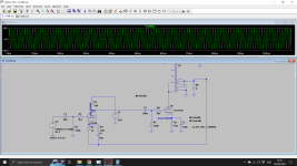
Greetings Friends. I've been fascinated by the 6C33C since I first laid eyes on it, and I've been kicking around an idea for a simple SET amp featuring the triple nipple. Borrowing the driver (and schematics) from the 6336 SET Amp by @Suncalc this amp uses cathode bias and the high voltage swing driver to make ~15 watts of Class A power.

Edcor's CXSE25-600 is a 25-watt OPT with a 600 ohm Primary and 8 ohm Secondary. According to my dummy math, 360v to the OPT will give a Va-k of 250v and a Vk of 88v, with a 400 ohm Kr.
Eliminated the volume control from the input, replaced with a 250k resistor.
Grid Leak Resistor for the output stage changed to 200k. Grid Stopper necessary?
Not sure how to calculate the K bypass cap.

Surprisingly the Hammond 372JX provides all the power needed. The output stage's cathode resistor eats so much b+ that there's no problem getting the 300v for the driver stage.
Enough capacitance for such a large current draw?
Better to take the driver stage power from before or after the 2nd choke?
Thoughts?
thanks for taking a look!
w
Edcor's CXSE25-600 is a 25-watt OPT with a 600 ohm Primary and 8 ohm Secondary. According to my dummy math, 360v to the OPT will give a Va-k of 250v and a Vk of 88v, with a 400 ohm Kr.
Eliminated the volume control from the input, replaced with a 250k resistor.
Grid Leak Resistor for the output stage changed to 200k. Grid Stopper necessary?
Not sure how to calculate the K bypass cap.
Surprisingly the Hammond 372JX provides all the power needed. The output stage's cathode resistor eats so much b+ that there's no problem getting the 300v for the driver stage.
Enough capacitance for such a large current draw?
Better to take the driver stage power from before or after the 2nd choke?
Thoughts?
thanks for taking a look!
w

Are you sure that resistance of the OPT's primary winding is 400?! If so, I'm not sure this transformer is suitable for that high of power and low of impedance!
Another thing is that 12AU7 driver; I've built the 6336 amp and that drive wasn't able to provide enough current for grid of 6336 triode, so I guess 6C33C would be the same and it will cause HF roll off.
However, I did some changes to the original schematic and was able to improve hi F with biasing the driver stage hotter. Surprisingly distortion and performance got better too:
Hi everyone, after weeks of tweaking this amp finally I was able to get the best out of this tube, now it's one of the best SET's I've ever heard.
Here is the final schematics and test results:

.jpg")


Here is the final schematics and test results:
Oh, I'd forgotten about your post on the exact same subject. Hope it sounds good.
Here's the page on the Edcor transformer. It's 600 ohm @ 25 watts. I'd assumed it was designed for this task.
More current for the driver? I have 6N6P, could that work?
Thanks!
w
Here's the page on the Edcor transformer. It's 600 ohm @ 25 watts. I'd assumed it was designed for this task.
More current for the driver? I have 6N6P, could that work?
Thanks!
w
My first thought is that you might consider a lower value grid resistor in the 6C33C and either a (much) beefier driver tube to suit or a solution like Tubelab's Power Drive.
Oh sorry my bad! I thought you were talking about OPT. The OPT seems to be okay, but running 250V Va is the absolute maximum for 6C33C.Here's the page on the Edcor transformer. It's 600 ohm @ 25 watts. I'd assumed it was designed for this task.
More current for the driver? I have 6N6P, could that work?
About the driver, I think you should experiment with different ones. first start with the original schematic then use my version, and if it is still lacking high end you should use another triode, or maybe a triode strapped pentode like EL84.
Attachments
I tend to agree putting more current through the second stage will help overcoming the miller cap of the 6c33. The gain of the tube is low so miller is not such a big problem. You have about 50pF max to drive so that's 63K max impedance from the driver (-3dB @ 50KHz) - well within a 12au7. So sticking with a 12AU7 is fine as in #3. The triode mode offers reasonable damping factor on the speaker without NFB, and you could apply GNFB easily to the circuit if you so wished.
I did a PP amp with 2x6c33 and that gave 100W rms. The supply was higher as the 6C33 was dissipating < 30W. The tubes are extremely robust. It did use a pentode driver which had distortion cancellation with the screens taps from the output plates. However for SE operation the phasing is wrong.
The u is very variable 2.5..4 so you may struggle to get full drive on certain tubes.
Some time ago I prototyped a 6C33 PP amp.
The design is unusual in that the output plates provide local negative feedback to the screens of the LPT driver stage. With the right choice of pentode here, the triode non-linearity can be largely be corrected. In the end I went with Smoking-amp suggestion of using a pair of 6197’s as drivers which can cope with the output swing needed. For a totally valve solution the cathodes could be returned to the negative rail with a resistor.
The input stage is hum-buck allowing the input screen cable to float slightly avoiding hum loops with external...
- baudouin0
- Replies: 4
- Forum: Tubes / Valves
Last edited:
These super low mu output valve designs trade off OPT performance (lower turns ratio and lower impedances both scale to better OPT performance) in return for greater drive voltage requirements. Your post #1 schematic needs a nominal 175 Volts peak-to-peak drive to the output valve grids, linearly, and that's where your effort must be applied. Miller C is low (mu of 2 or something), so a reasonably high impedance, allowing for output valve grid leak resistance, driver can work. Goes without saying that 300 VDC B+ isn't enough for a linear 175 Vp-p, so a higher supply voltage is the starting point.
Yeah, they didn't do that in the 1950s. They also didn't try to use regulator pass valves as outputs. The whole amplifier design rests in the driver.
All good fortune,
Chris
Yeah, they didn't do that in the 1950s. They also didn't try to use regulator pass valves as outputs. The whole amplifier design rests in the driver.
All good fortune,
Chris
That was my issue Chris I actually needed a higher supply voltage for the driver. Otherwise grid voltage would never reach 0V on certain tubes limiting the output power. I needed 250V peak-to-peak, but my 6c33 HT was 310V and they were biased cold (fixed bias) at -125V or so. The drivers needed 380V.
I once tried a EL84 triode strapped as the driver, loaded with anode feed choke and around 250V B+ for both 6C33C and EL84. The performance was so bad, and THD was around 10% at only 6W!
Then I changed the choke with a mosfet gyrator and it did help a lot, but I didn't like the sound and gave up on 6C33C SE once for all!
Then I changed the choke with a mosfet gyrator and it did help a lot, but I didn't like the sound and gave up on 6C33C SE once for all!
I'm trying to encourage folk who want to explore these super low mu valves to shift their design emphasis from the output stage, relatively trivial, to the driving stage. This is the same issue that folk face in McIntosh and Circlotron designs, which also have a gain of 2, and need the same or similar solutions.
Just because commercial designs of the Golden Age (Praise God!) used driver B+ supplies derived from the output valves' supply doesn't mean we have to do the same. This is DIY audio, and the emphasis is really on the Y. A second, higher voltage but lower current, power supply is trivial these days, and gives other benefits of isolation, yada yada. Choose life! (Sorry; reference Trainspotting opening monologue)
All good fortune,
Chris
The driver which I posted in #3 is able to provide 180V p-p for the output tube and its output impedance is around 10k. It works perfect for 6336 triode, but I don't know if it suits 6C33C.
The funny thing is the distortion, at first I built the 6336 using #1 driver and hi F roll off was a little too much, here is the frequency response and THD:


Then I changed the second 12AU7 bias point according to #3 and here is the results:
.jpg")

I still don't understand how THD got lower?! Because I was expecting more distortion due to second stage 15k anode resistor instead of the original 100k.
The funny thing is the distortion, at first I built the 6336 using #1 driver and hi F roll off was a little too much, here is the frequency response and THD:
Then I changed the second 12AU7 bias point according to #3 and here is the results:
I still don't understand how THD got lower?! Because I was expecting more distortion due to second stage 15k anode resistor instead of the original 100k.
I would say the 15K load resistor is a bit low in #3 to get full swing out of the 12AU7 looking at the load lines without grid conduction. Maybe 33K better.
Sorry I stand corrected 180v pk-pk is what it gives with the tube saturating at 100V.
With 33K and 2k2 cathode you get 250v pk-pk.
The E88CC is more linear at higher currents.
With 33K and 2k2 cathode you get 250v pk-pk.
The E88CC is more linear at higher currents.
I made SE 6S33S in 1993. Vaa=3ooVdc. 3 stages. 6SN7GTB parall (20ma total)+6BX7parall(40ma total) +6S33S(330ma).Grid leak resistor for 6S33S MAX value
50K(Japanes sugestions). I wound OT 1,2K:6R.Sound fantastic.
Instead 6BX7 as diver,I tried 6SN7GTB and 6N6P both parallel but they were not capable to drive 6S33S properly.
50K(Japanes sugestions). I wound OT 1,2K:6R.Sound fantastic.
Instead 6BX7 as diver,I tried 6SN7GTB and 6N6P both parallel but they were not capable to drive 6S33S properly.
- Home
- Amplifiers
- Tubes / Valves
- 6C33C SET Monoblock