Looking to build a 6BX7 tube amp in the style of Jeff Larson ---- any diagrams or amp info
would be appreciated. This community was most helpful in my (OUR) restoration of my Charlie King 6B4 amp ---I want to do the same for Larson
in advocating his amp building talents...... We can't let this legacy fade especially as OB's are now so popular -- my focus is on the amp as described on Glow in the Dark ( thank you for that information ) ....... James from T Town Oklahoma......
Dave, I must realign my statement..... the amp build is my 'amp project' as I am talking this up to my local amp talent. Looking for a schematic to help get this going--- James
Forget about the PP 6BX7 & 6BL7. I put together a test amp not so long ago to test those in PP.Looking to build a 6BX7 tube amp
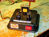
As well as the 6SN7. The same socket fits the 5998, so ran that too. I called the beast 'The Betty Crocker Special'.
Because the test amp was built on an inverted cake tin. Not recommended, something I'd seen in seen
in Joe Roberts 'Sound Practices' magazine about 25 yrs ago.
The results all summerized here on DIY as follows, running in Class A & without exceeding the dissipation limits
the power output just before clipping was 3W for the PP 6BX7 & 6BL7 & 10W for the 5998.
The 6SN7 was One Watt, but finding a suitable OPT for the high RL is difficult.
A pair of 6EA7/6EM7 with their large triodes in PP managed 7W, no problem. Same octal appearance on the chassis.
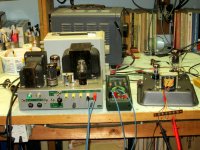
IMD test with on one of the 6EA7 Amps. One of many still on pages here on DIY, have a look.
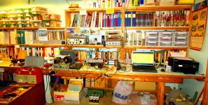
The test amp is not built for appearance.. It is a test amp.
Attachments

PP 6EA7 Amp X……….First Pass
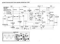
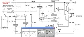
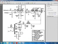
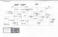
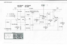
The schematic looks rather busy, here is an explanation covering the main points.
The Amp simulation is run in Electronic Workbench (EWB). The test amp was powered by 60 yr olde lab supply with variable +HV & -150V. The posted test results are all labeled (I think). The label ‘GAIN ~7’ was from a previous related Sim & should have been dumped from this.
Keys on the Laptop Keyboard operate switches as follows
Key A sets the input signal on or off.
Full output requires about One Volt at the grid of the first triode in this configuration. So should cover most common sources we see here on DIY.
This version of the amp uses a simple diff amp at the input, the cathodes to -14V thru an NPN 2N2222 that was in my pile.
I tried several other input cct arrangements including cathodes to -150, cathodes to common & ordinary split load phase inversion. Guess I like this one best because of something called Common Mode Tolerance.
Key X sets a common cathode resister or separate
I tried setting one of the 6EA7 power triodes specs off by something like 20%. The objective was to determine how effective separate cathode resisters are. I’ll find some of those numbers later. Proving again there is a strong case for separate cathode resisters.
Key Z inserts the OPT primary resistance in or out of the cct.
The sims I got here would have been more accurate had the OPT secondary resistance been included. And something for iron losses.
You can expect better results by using an OPT section wound rather than the universal Hammond OPT I used for these tests. But the common distortion measured results might convince some to try lesser OPTs.
The total Pd’s for the 6BX7 or 6BL7 is 12 Watts. The total Pd’s for the 6EA7 version is 22 Watts. We can get about twice as much audio from the PP 6EA7 version.
In Class AB even more at greater distortion. And without NFB, not as good a Damping Factor.🙂
Attachments

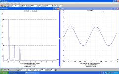
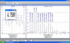
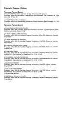
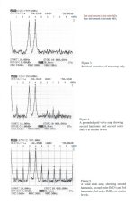
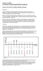
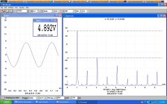
Graeme Cohen of Australia devised a a test method that measures both THD & IMD simultaneously.👍
I've used this method often with good results. The test signal frequencies used are a ratio of 3:4.
For the test on the 6EA7 PP Amp I used frequencies of 1.5 & 2.0 KHz.
I've used this method often with good results. The test signal frequencies used are a ratio of 3:4.
For the test on the 6EA7 PP Amp I used frequencies of 1.5 & 2.0 KHz.
Attachments

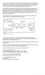
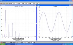
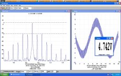
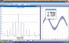
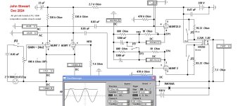
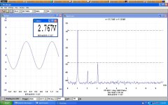
Common Cathode Resister vs Separate
The objective of this test was to check how effective separate cathode resisters are to equalize the resulting cathode currents as tubes age.
The Switch ‘X’ sets the condition.
For the test the emission of the upper 6EA7 power triode was set 20% low while leaving the other parameters as is.
For the common cathode resister the ratio of the cathode currents was 47.3/37.2……...1.27
When separate cathode resisters were switched in the ratio dropped to 42.8/41.4……….1.03
Separate cathode resisters are very effective.
Attachments
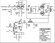
Back in the day I built a PSE amp with a 6SL7 and parallel single ended 6BX7. Output xfmr was 2.5k 10w single end. 6BX7 set at 40ma with 470 ohm 10w reostat set for proper current (270~280 ohm) if I remember. Put out about 4~5 watts.This was magic powering a poor man's VOT...15" EV and 808 Altec in a pair of woofer cabinets that a bar was throwing out. Put the 808 in a single 203 horn that I cut into make two single sections. If I can dig up the schematic for the amp I will post it.
30 years or so ago I built a push pull 6BL7 with a 6SL7 floating paraphrase splitter. I can't remember voltages or current but would have run them as hard as the book said was okay. It sounded nice on some Snell E3.
Was it one of these? Electra Print is in the Transformer business.
In these they score two transformers & a Tapped Choke.
Then its up to the builder to get the claimed performance.
There is no information on how they get their numbers.
I found by careful measurement running Class A in PP &
without exceeding dissipation limits PP 6BX7 clips at 3 Watts.
And checked that with a five & half digit Gossen Precision
DVM & Wattmeter. When I post results on DIY you can believe them.🙂
Attachments

More from the Archives on the PP 6BL7 Tests. Already several years back here on DIY, 2019.
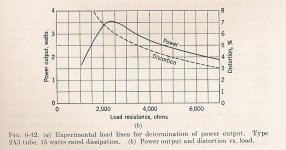
For triode designs SE or PP I've always used the information from EE text books of that era,
they show a proof of Power Output vs Load Resistance, And Distortion. Looks like Rl
about 3X or more than rp would be a good choice. More power is available at a lower Rl,
but are we building a book shelf amp or a PA system?
So the audio power at clipping goes from 3W to 4.9W, about 10 db. But probably more 3H.
The test mule was rewired for a 6EA7 version a while back, so can't check for THD today.
The same 2H curve in SE become a 3H curve-in PP. More power than 2X in the SE hookup
by choosing a load line a little steeper. But that could go too far. Many listeners find 3H
objectionable.
So here in a comparison of PP 6BL7 using 21K & 15K loadlines.
Too me the 6BL7 is a 6SN7 on steroids. But it ihigh mu, so requires a higher voltage to run as
a simple power amp. The 6EA7 version has power triode of much lower mu, that simplifies
the power supply quite a bit. And the finished amp looks the same as with 6BL7s
for those who worry about appearance.
Looks like I've got one of the two PP UL 6L6GC amps I built around 1960 on the bench that day. 🙂
Attachments
-
6BL7GTA.pdf332 KB · Views: 28
-
6BL7GT.pdf140 KB · Views: 41
-
 IMG_6445 to 6446 Test Bench 16W 20C.jpg539.7 KB · Views: 28
 -
 PP 6BL7 3.2 W THD.JPG141 KB · Views: 26
 -
 PP 6BL7 One Watt THD.JPG137.4 KB · Views: 33
 -
 PP 6BL7 Amp at 4.9 Watts w 15K P-P Load.jpg403.9 KB · Views: 44
 -
 PP 6BL7 Amp at 3 Watts w 22.5K P-P Load.jpg423.7 KB · Views: 41
 -
 2A3 Triode Distortion.jpg119.7 KB · Views: 28
 -
 25W Amp Front.jpg67.3 KB · Views: 27
I thought that when power is doubled (a 100% increase) that the result was an additional 3 db of output. A 1.9w increase from 3w is only 63.3% so shouldn’t that result (3db x .633) in an increase of 1.9 db?So the audio power at clipping goes from 3W to 4.9W, about 10 db.
That would be the equivalent of moving ~26” (0.66m) closer to the speaker of the 3w version. Subjectively, that’s not a very significant increase in perceived volume. Barely noticeable, really.
There are two proofs here. One is that someone still reads my stuff. Thank you Charlie.
And good to hear from you, I don't get on DIY as much as I once did.
The other is that as one gets olde it is easy to screw up, So I will blame that on being rode hard
& put away wet at 92 yrs olde,
The increase in power is 10 log of P2 / P1. So 5db. Maybe not worth doing, except for bragging rights!
In 1956 I built a very simple PP 6AQ5 Amp. With a Hammond 1618 OPT. But it has a preamp for a low level pickup
that ran on a cheap Webcore Turntable. On the bench it doesn't test well.
But when I took it to parties with a stack of LPs & 45s no one cared after a couple of beers! How times change.👍👍
- Home
- Amplifiers
- Tubes / Valves
- 6BX7-6BXL SET amplifier for audio