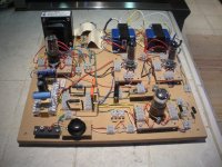
Yes I'm still working on the SE 6BQ5 amp. I should have it running an a couple of days.
I thought this may be a good time to look into how to regulate the screen voltage on Pentodes. The power supply I modeled in PSUD II looks stable but I will know more once I run the amp.
Is there a simple (something a Newbie would understand) solid state way to regulate screen voltage?
Would it help the performance?
A simple zener (stack) with a resistor should do fine for g2 regulation. Lots of info available, see e.g. here: Zener Diode Voltage Regulator - Electric Circuit
Or use the 6BQ5's in triode mode, but I assume you already have your OPT's, which might get you into trouble if you decide now to change the required load impedance 😉
Or use the 6BQ5's in triode mode, but I assume you already have your OPT's, which might get you into trouble if you decide now to change the required load impedance 😉
A quick examination of tube characteristics shows that regulation makes a VERY big difference in pentode circuits.
I use a simple Maida reg, very inexpensive, excellent regulation, and more than quiet enough for this application. You can swipe the reg design right out of the Red Light District amplifier.
I use a simple Maida reg, very inexpensive, excellent regulation, and more than quiet enough for this application. You can swipe the reg design right out of the Red Light District amplifier.
A pentode screen is both an input and an output. If there is significant impedance there, the output current will generate a voltage which will then be fed in again. This would simply be a source of harmless negative feedback if a pentode was linear. Pentodes, like all valves, are not linear but have a lot of second-order distortion. This second-order, if fed back into g2, mixes with the input signal to create third-order (etc.). In most cases this extra 3rd will be in phase with the intrinsic 3rd produced by the pentode anyway.
Class A SE might not suffer from this effect too much, as at least the pentode will be biased in a reasonably linear part of its characteristic. It gets serious for P-P Class AB/B. Similar issues arise for tetrodes, and tests on RF linears have shown that g2 needs to be fed from a very low impedance: a string of zeners is not good enough, although still popular.
Class A SE might not suffer from this effect too much, as at least the pentode will be biased in a reasonably linear part of its characteristic. It gets serious for P-P Class AB/B. Similar issues arise for tetrodes, and tests on RF linears have shown that g2 needs to be fed from a very low impedance: a string of zeners is not good enough, although still popular.
: a string of zeners is not good enough, although still popular.
Putting an Transistor on top of the zeners helps(Mosfet preferred).
How? The problem is the dynamic resistance of the zeners. The exact voltage at g2 does not matter too much, but it must not vary at audio or envelope frequencies.
Putting an Transistor on top of the zeners helps(Mosfet preferred).
I use a mosfet source follower biased by a zener or gas tube string. A pot can be used to allow for voltage adjustment. One of my recent projects uses 8 6BQ5's. I use a single zener string feeding 8 seperate mosfets. There are 8 pots tied across the top zener, each feeding a seperate mosfet, which feeds its own screen grid. It is a simple but very effective circuit that allows for individual tube current tweaks since the cathode voltages are all fixed at 12.5 volts.
Yes, a zener feeding a follower solves the problem. A fat capacitor might do instead, as the main issue is dynamic impedance not exact bias voltage.
Tubelab, that's a very nice little trick for multiple tubes, I like it.
I suspect that the original request was for just a simple single SE, so in the interests of keeping it simple, a resistor and decoupling cap will be perfectly sufficient (or just tie the screen to supply).
I suspect that the original request was for just a simple single SE, so in the interests of keeping it simple, a resistor and decoupling cap will be perfectly sufficient (or just tie the screen to supply).
A quick examination of tube characteristics shows that regulation makes a VERY big difference in pentode circuits.
I use a simple Maida reg, very inexpensive, excellent regulation, and more than quiet enough for this application. You can swipe the reg design right out of the Red Light District amplifier.
Would it make sense to incorporate a Maida reg. into pretty much any PP Pentode/Beam Tet. screen grid supply? I am thinking of this project in particular...
http://www.diyaudio.com/forums/tubes-valves/156699-mullard-5-20-kt88-pp-blocks-22.html#post2412001
..Todd
Todd, the one you linked to is ultralinear. For a pure pentode amp, I think the Maida is all around the best choice- and it's really no more complex or expensive than a Zener string and emitter follower, but much better performance.
I see. I thought "pentode" was referring to the tube itself rather than its mode of operation. Thanks, this thread is making more sense to me now.
..Todd
..Todd
Last edited:
I suspect that the original request was for just a simple single SE, so in the interests of keeping it simple, a resistor and decoupling cap will be perfectly sufficient (or just tie the screen to supply)......For a pure pentode amp, I think the Maida is all around the best choice-
The original request did state an SE amp in pentode mode. It is possible to tie the screen to B+ in some EL84 / 6BQ5 circuits. I can not do that in my amps since I am running the plates at 430 volts. The screens would dissapear rather quickly at that voltage. This is the case with all sweep tubes and some of the popular audio tubes. In any pentode amp the plate current is dependent on the bias voltage on G1 and the screen voltage (G2). The plate voltage has only a small effect on plate current.
In a small SE amp that has no regulation on the negative bias (G1) supply an unregulated screen isn't a bad idea. That way the two unregulated supplies affect the tube current in different directions as the line voltage changes. In extreme versions of Petes red board the plate current will go down as the line voltage goes up. Why? Because the screen is regulated and the bias supply is not.
If you have decided to regulate the screen voltage, the zener - resistor circuit, the zener - resistor - mosfet circuit, and the Maida regulator are all valid choices, each with their own advantages.
The zener - resistor circuit is simple, and the resistor can be chosen such that the screen voltage will drop in extreme overload condition, possibly saving the tube. The voltage is fixed by the diode (or gas tube) choice. The output impedance is equal to the sum of the zener diode impedances. It can be lowered at AC with a capacitor (good idea).
The addition of a mosfet will allow regulation over a wider range of currents and the output voltage will remain constant at any current that doesn't blow the mosfet. This is what is used in Petes red board. The voltage is fixed by the diode choice, unless a pot and a second diode is used. The output impedance is at least an order of magnitude lower than the zener string alone.
The Maida is a fully regulated supply, it can be made adjusable with a pot, but the dissipation in the pot can be an issue. it has the lowest output impedance of all three choices.
So there are 4 possibilities and all or valid. Some are better suited than the others in any given design.
Thank's everybody for your input.
I realize that controlling screen voltage on this project is of questionable value. The number one "To Learn" item with this build is the impact the relationship between Plate V, Screen V, and Idle Current have on performance. I thought this would be a good time to add Screen Voltage Regulation to my "To Learn" list. It will definitely be of more value when I move up to bigger amps.
My plan is to adjust the screen voltage and idle current and see what the impact is on sine and square waves. I hope this will help at least a little. It will have to do until I can get access to a Distortion Analyzer.
SY: Thanks for the lead to your RLD amp. I gathered the info but will need to study for awhile. My current knowledge of SS devices is 0 to None.
George: A simple sketch and part numbers would be a big help. I can work on learning about them at the same time.
Once again,
Thanks
Attachments
Copy the design right out of Petes red board amp.
http://www.diyaudio.com/forums/tubes-valves/151206-posted-new-p-p-power-amp-design.html
DCPP Amp
The circuit you want is on the power supply schematic, the box in the center labled G2 regulator. R21 is just there to limit the dissipation in the mosfet and can be eliminated (shorted) in your application. The series zener string (D5, D7 and D8) sets the output voltage. The voltage will be the sum of all the zeners plus the gate voltage of the fet (about 10 volts).
Just about any N channel fet in a TO220 package that can handle 400 volts or more and a few watts will work. I like to use the ones that are competely plastic coated to avoid shocking moments when touching the heat sink. I used Toshiba 2SK3563. D6 can be eliminated if the mosfet has internal gate protection zeners. C21 and C22 are not critical use anything from 4.7 to 47 uF. R33 and C22 determine the start up time. This allows a slow start up even if using solid state power rectifiers.
Here's a Maida regulator circuit I was working on for an upcoming project. It's not tested yet though, so no guarantees I haven't made a mistake somewhere. (I drew it using illustration software not schematic capture or PCB CAD software, and doing it this way is awfully error prone.)
It's close to SY's RLD Maida reg. but uses a FET for pass device. There's a web address listed on my drawing that explains it all. That's where I got the circuit from.
There's 2 PCB layouts, one just uses bigger (TO-247) FETs (which I have an abundance of in my junk box).
..Todd
It's close to SY's RLD Maida reg. but uses a FET for pass device. There's a web address listed on my drawing that explains it all. That's where I got the circuit from.
There's 2 PCB layouts, one just uses bigger (TO-247) FETs (which I have an abundance of in my junk box).
..Todd
Attachments
Last edited:
You'll want C3 to be a lot larger- an aluminum electrolytic from 20-50uF works really well for that. A "high quality" cap like a polyprop is not good for stability.
C2 is nice for lowest noise, but for output tube screen regs, that's not particularly important.
C2 is nice for lowest noise, but for output tube screen regs, that's not particularly important.
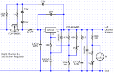
Here is a somewhat-adjustable Maida-style regulator that I built for another amp I am working on. It's based on the original data sheet, plus a few tricks I picked up on this forum. It is being used for screen regulation. I needed the range to allow me to experiment with lots of different tubes. The amp isn't done, but the power supplies have all been tested. It seems to work as designed and gives me some range to play with. Obviously, the FET will be dumping a lot of heat at lower voltages in my case.
As George said, you have to be mindful of dissipation through the various resistor and zener strings at both ends of the adjustable range. Here I have made an effort to minimize what the pot has to deal with. I made a spread sheet to help with this so that I could play around with the fixed resistor values to fit what I had on hand and control which components had to deal with burning watts, while giving me the range I wanted.
As George said, you have to be mindful of dissipation through the various resistor and zener strings at both ends of the adjustable range. Here I have made an effort to minimize what the pot has to deal with. I made a spread sheet to help with this so that I could play around with the fixed resistor values to fit what I had on hand and control which components had to deal with burning watts, while giving me the range I wanted.
Attachments
- Status
- Not open for further replies.
- Home
- Amplifiers
- Tubes / Valves
- 6BQ5 Screen Voltage Regulator