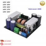
Have bought one of these SMPS on eBay:
https://www.ebay.com/itm/154164805607?hash=item23e4f03fe7:g:uzgAAOSwlxRfVvpt
I actually also have one running +-70V and a new one for +-35V, all for supplying class d amps.
The +-70V one did work and is running in my main amp right now. I checked the additional supply voltages, and was a bit surprised they where a bit off, not delivering +-12V or +12V, as I recall they where a bit higher, but thought this was down to these to being regulated, and as I'm regulating the +-12V down to +-6V on the amp board, and as the +12V which I referenced to the -70V for supplying the Gate driver, it all worked fine.
But with the +-35V supply, I'm getting only +-6V and +6V!!!!!
Anyone have the same experience with these SMPS?
I'm wondering if the transformer is the same for all the different output voltages you can chose from?? Or whether this is a fault altogether.
As the output is not regulated you'll need more windings for getting 12V on the +-35V SMPS, than for the one giving +-70V!
There is a small resistor on the bottom side of the pcb, and I'm wondering if this is actually how they change the main output voltage, and that this is not done using different transformers!
Attachments
Hello.
Don't get this the wrong way but how hard can it be to simply follow the copper traces from the auxiliary outputs, to get a simple block diagram of what and how they are done?
As i see in the pictures, it is a rudimentary PSU, absolutely bare minimum, thus it cannot be that hard to reverse engineering.
PS: 45$ for a 600W switching power supply? really?
Why do people buy this crap?
The answer is they are junk and you get what you pay for. Switching supplies usually use a resistive divider for feedback to regulate the output.
Isn't it?Not really an answer to my post I think .... 🤔
Look at the PSU's pictures, it's as basic as it gets, despite the black silkscreen you can still see the copper traces well enough, thus you can easily reverse engineer it.
What tests have you done on it thus far?
Well it might me just me, but a reply saying: Why do people buy this crap? .... is less than constructive, and not really a way to get a good conversation started.
The question was; has anyone else had the same experience with these SMPS'? Having too low aux voltages with the lower voltage SPMS'?
And secondly, a question about the production or finalization, to accommodate the many options for "primary" voltages, whether this is just done by changing the FB resistor or actually done by also changing the transformer?
I'm aware that this is of course not a high end SMPS, that you could use in the space industry, and I have no misconceptions about the max output and that the 600W is probably set at least 2x the actual usable limit.
To the power, to be fair the add says that the continuous power at 25C is "only" 300W, and that is should probably also be treated with some caution.
Used in an amplifier, not intended for pro use, I think using this for up to 2x300W amp in 8 ohm is ok, but not more.
For this particular project though I was intending to use this to drive a single active PC speaker ..... it will never break a sweat on this 🙂
As for it being Crap or not, and being basic. Crap, well besides the fact it seems that the aux voltages will not be near the speced 12 V for a very low voltage version, and probably the same (just higher than 12V) for the higher voltage versions, Looking at the component and build quality, I think it looks at least as good as what you find in all the commercial products we all have at home. The trafo seems the same as used in the larger versions of the product, so for the 600W version it seems ok. It uses Litz wire to reduce skin effect. The PCB is double sided (yes the black color is just to make it look cool). Output rectifiers are MURF1620 (16A 200V). It is not possible to determine the fets as the number is erased. The controller is also without a number, but is in a so16 case. The controller is placed on a small daughter board. It has inrush NTC. It has a small fuse. Iput filter, with appropiate film caps. The bridge looks a little small, but probably quite ok for this size smps. DC caps in input are chinese 105 deg ones, same for the main output. A bit on the low side of capacity, and unknown ESR (which for the output is more important. For the aux there is United Chem KY caps. Cooling fins seems ok for this size of smps, being more 300W than 600W mind you.
What would you have done much differently?
Just saw that these are also sold in EU by Audiophonics.fr
And lastly why chose this. Firstly not many SMPS have 5 outputs optimal for single bridge class d; main +-, Aux +- for input circuit, and +12V independent for the gate drivers (need to be referenced to main minus). Secondly, yes the price is really good for small projects.
I know i may have seamed a bit rough but as it happens i design and built high performance SMPS ( both low and high power ), so i was speaking from experience. For instance this is one of my creations ( schematic and pcb design, and also assembly, all done be me ):
https://i.postimg.cc/gkyF0MZK/001.jpg
1500W SMPS with active PFC, just over 90% overall efficiency at maximum power...
And when i say it does 1500W i mean nonstop power.
But it's BOM cost alone is more than 200$...
That is why i said those things, good quality comes at a price, and i would not use those cheap chinese stuff unless i had absolutely no other choice.
Now we talk about it, do so,eone now where to buy transformers? And crap, yes it can be that way, but LLC circuit is circuit, feedback
for audio purposes is not that wise, it is far to slow for transients, and as such we place resonance point at a best place so it stays quite stable without feedback in open loop, then it does react quick. sheap is not always bad, design pcb is important and sometimes bad done..
for audio purposes is not that wise, it is far to slow for transients, and as such we place resonance point at a best place so it stays quite stable without feedback in open loop, then it does react quick. sheap is not always bad, design pcb is important and sometimes bad done..
There are some readily wound LLC xformers available at Würth Electronic. Btw, I configured my LLC-converters the same way. Being unregulated this is the modern replacement for unregulated toroidal supply with improved properties.Now we talk about it, do so,eone now where to buy transformers? And crap, yes it can be that way, but LLC circuit is circuit, feedback
for audio purposes is not that wise, it is far to slow for transients, and as such we place resonance point at a best place so it stays quite stable without feedback in open loop, then it does react quick. sheap is not always bad, design pcb is important and sometimes bad done..
Oke thanks.
Yes regulation for output stages is not needed, the feedback can never be fast enough for transients. The china version
I did see is reulated, maybe change this to unregulated is a better way, not that hard.
I goo look at Würth.
Yes regulation for output stages is not needed, the feedback can never be fast enough for transients. The china version
I did see is reulated, maybe change this to unregulated is a better way, not that hard.
I goo look at Würth.
Wow... What a toxic bunch of thread crapping?!?! Someone asks a question about a switching power supply and gets pummeled with everything except a helpful answer.
My apologies for not having an answer either, but after reading this thread, I couldn't help but play white knight....
My apologies for not having an answer either, but after reading this thread, I couldn't help but play white knight....
Check output diodes solder joints, transformer, I do not now it is a smps with feedback? but as a resonance version you need to check
the frequency of the circuit, if it is to low or to high, if this is oke, the supply contains properly a wrong transformer or some parts are fake.
When the frequency is to high or to low, wrong cap/resistor osc setting on gate driver chip. Here it looks like
it is fabricated with wrong parts or some are fake. measurements are the solution. these smps are not that complicated.
With a scope you can look, be careful with probes and a direct connection to grid.
Certainly the most helpful posting here😆Wow... What a toxic bunch of thread crapping?!?! Someone asks a question about a switching power supply and gets pummeled with everything except a helpful answer.
My apologies for not having an answer either, but after reading this thread, I couldn't help but play white knight....
- Home
- Amplifiers
- Power Supplies
- 600W LLC Power Amplifier Switching Power Supply .... not giving the correct secondary voltages!