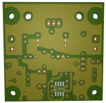
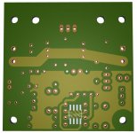
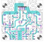
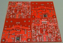
My take on board layout for Jung/Didden regulator (shematics as version V2.2)
Features:
• Universal pos/neg board on 5x5cm 2 layer board
• Multifootprint Capacitors Ls 2.5mm - 5mm
• Separate Power, Signal, Sense Ground, connected at output cap
• JP1 JP2 configure board as positive/negative (switch opamp power supply pins), short - for negative board, short + for positive board
• JP3 JP4 off remote sense, on local sense
• DIP (top layer) or SOIC(bottom layer) opamp package
• Bottom mounted SOIC opamp is preffered, protected against noise with ground pours on top & bottom layer & bottom of the case
• For negative board you must reverse all polarised elements (capacitors&diodes) and use complementary transistors
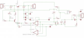
Schematics and BOM are the same as offical V2.2:
Link to Shematic&BOM: http://jandidden.com/linearaudio.nl/images/pdf/superreg_article_V2_2.pdf
Alternate link: https://drive.google.com/file/d/0BxF_x0eVgXlGY0J1dmVpakJ0Smc/view
Features:
• Universal pos/neg board on 5x5cm 2 layer board
• Multifootprint Capacitors Ls 2.5mm - 5mm
• Separate Power, Signal, Sense Ground, connected at output cap
• JP1 JP2 configure board as positive/negative (switch opamp power supply pins), short - for negative board, short + for positive board
• JP3 JP4 off remote sense, on local sense
• DIP (top layer) or SOIC(bottom layer) opamp package
• Bottom mounted SOIC opamp is preffered, protected against noise with ground pours on top & bottom layer & bottom of the case
• For negative board you must reverse all polarised elements (capacitors&diodes) and use complementary transistors
Schematics and BOM are the same as offical V2.2:
Link to Shematic&BOM: http://jandidden.com/linearaudio.nl/images/pdf/superreg_article_V2_2.pdf
Alternate link: https://drive.google.com/file/d/0BxF_x0eVgXlGY0J1dmVpakJ0Smc/view
Attachments


Last edited:
Take a look at the original PCB's which Jan designed -- shown on post 786 of this thread:
http://www.diyaudio.com/forums/power-supplies/20937-super-regulator-collecting-facts-79.html
Don't use the ground plane for power and sense connections.
http://www.diyaudio.com/forums/power-supplies/20937-super-regulator-collecting-facts-79.html
Don't use the ground plane for power and sense connections.
Don't use the ground plane for power and sense connections.
OK, thanks. May I ask why?
Take a look at the original PCB's which Jan designed -- shown on post 786 of this thread:
http://www.diyaudio.com/forums/power-supplies/20937-super-regulator-collecting-facts-79.html
Don't use the ground plane for power and sense connections.
Better?
Attachments
Refrain from placing the ground plane underneath the heatsink of the pass transistor.
Jack, what's the concern?
Refrain from placing the ground plane underneath the heatsink of the pass transistor.
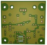
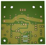
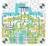
Underneath the heatsink, this is not ground plane, this is input and output Voltage traces.
Ground traces/pours are on the bottom layer.
Power gnd trace (line) and signal gnd( pour around SOIC opamp), they are connected on top layer with trace between C4 and C9 - pins.
Power gnd trace (line) and signal gnd( pour around SOIC opamp), they are connected on top layer with trace between C4 and C9 - pins.
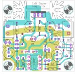
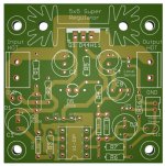
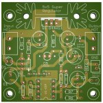
Final version
I will post gerber for this PCB to DirtyPCBs.com
- Separated opamp supply ground & voltage reference ground (C9, D5)
- All grounds star connected on output cap ground pin
- Current source ground (R2) have option to connect to input cap ground pin or output cap ground pin
I will post gerber for this PCB to DirtyPCBs.com
Attachments

Sikahr,
are you able to check that the PCBs offered by Dirty Cheap are correct and fully working when filled with components?
Did you buy your prototypes from them?
are you able to check that the PCBs offered by Dirty Cheap are correct and fully working when filled with components?
Did you buy your prototypes from them?
Waste of Time
As there is no circuit diagram link that works. I'd rather pay more for a verified
BOM and insertion diagram.
Sikahr,
are you able to check that the PCBs offered by Dirty Cheap are correct and fully working when filled with components?
Did you buy your prototypes from them?
As there is no circuit diagram link that works. I'd rather pay more for a verified
BOM and insertion diagram.
Hi Andrew,
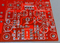
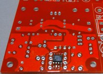
yes I order every board I posted on DirtyPCBs. I didn’t fill this board with components so I am not 100% sure it is working but I have plan to do it, I have board and all components but need time & welding spirit . I checked another board from DirtyPCBs (also mine) and it works flawlessly.
As for the general quality of DirtyPCBs check this link:
i/o blog: DirtyPCBs two layer ENIG PCB closeups
My opinion is, errors are possible, more or less, only on my design side, manufacturing is pretty good.
Attachments
As there is no circuit diagram link that works. I'd rather pay more for a verified
BOM and insertion diagram.
Choose for Yourself. 😀 (Schematics from Eagle included - please check if I made some mistake)
Schematics and BOM are the same as offical V2.2:
Link to Shematic&BOM: http://jandidden.com/linearaudio.nl/images/pdf/superreg_article_V2_2.pdf
Alternate link: https://drive.google.com/file/d/0BxF_x0eVgXlGY0J1dmVpakJ0Smc/view?usp=sharing
Attachments
Last edited:
Thanks
The links work now and I have made an order. Compared to Andrew T's boards, there is no floating pre-regulator which really helps and I may add these.
However, the board sizes are better although the pass transistor cannot be mounted as is on a metal chasis. The heat sinks shown are inadequate for higher current to 2A.
I have used Andrew T's 5V boards to drive 2.5 in SSD separately in PC audio and they work very well. Doing so makes a big difference to the quality of audio.
Choose for Yourself. 😀 (Schematics from Eagle included - please check if I made some mistake)
Schematics and BOM are the same as offical V2.2:
Link to Shematic&BOM: http://jandidden.com/linearaudio.nl/images/pdf/superreg_article_V2_2.pdf
Alternate link: https://drive.google.com/file/d/0BxF_x0eVgXlGY0J1dmVpakJ0Smc/view?usp=sharing
The links work now and I have made an order. Compared to Andrew T's boards, there is no floating pre-regulator which really helps and I may add these.
However, the board sizes are better although the pass transistor cannot be mounted as is on a metal chasis. The heat sinks shown are inadequate for higher current to 2A.
I have used Andrew T's 5V boards to drive 2.5 in SSD separately in PC audio and they work very well. Doing so makes a big difference to the quality of audio.
Could someone explain t me the difference the pre-regulator makes to this circuit?The links work now and I have made an order. Compared to Andrew T's boards, there is no floating pre-regulator which really helps and I may add these.
However, the board sizes are better although the pass transistor cannot be mounted as is on a metal chasis. The heat sinks shown are inadequate for higher current to 2A.
I have used Andrew T's 5V boards to drive 2.5 in SSD separately in PC audio and they work very well. Doing so makes a big difference to the quality of audio.
Andrew. Is there a link to your boards I can look at?
Simon
Sik gave links to his PCBs a few posts back.
They are being sold by "dirty".
I have never built, nor designed, a super regulator.
It is all down to Jung/Didden.
They are being sold by "dirty".
I have never built, nor designed, a super regulator.
It is all down to Jung/Didden.
Of course the Pass Q can be mounted on a bigger heatsink or mounted to the chassis side wall or floor...................... although the pass transistor cannot be mounted as is on a metal chasis. The heat sinks shown are inadequate for higher current to 2A....................
But, why would anybody want to use ~2A continuously from a super regulator?
Thanks Andrew.Sik gave links to his PCBs a few posts back.
They are being sold by "dirty".
I have never built, nor designed, a super regulator.
It is all down to Jung/Didden.
Sik. Thanks for your effort for providing this.
Soprry, different Andrew who used to come here
Details are in:
http://www.andrewweekes.talktalk.net/Manuals/ALWSR_rev2.9_Iss005s.pdf
You can still buy pcbs from the UK. I have made many and they work very well without a hitch, giving 4-6 uV noise over 1 to 1 MHz measurement range.
The preregulator gets rid of LF rubbish and helps maintain performance. It also ensures that there is a 3V input to the superregulator section.
Thanks Andrew.
Sik. Thanks for your effort for providing this.
Details are in:
http://www.andrewweekes.talktalk.net/Manuals/ALWSR_rev2.9_Iss005s.pdf
You can still buy pcbs from the UK. I have made many and they work very well without a hitch, giving 4-6 uV noise over 1 to 1 MHz measurement range.
The preregulator gets rid of LF rubbish and helps maintain performance. It also ensures that there is a 3V input to the superregulator section.
- Status
- Not open for further replies.
- Home
- Amplifiers
- Power Supplies
- 5x5 Super regulator