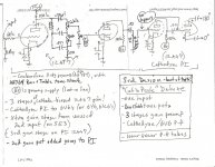
My "rockin" breadboard Deluxe phase inverter seems to be quite a bit unbalanced..... plate, screen and cathode voltages on both 6V6s are the same, and using 1% 1-ohm resistors on the plates give me 14W and 10W dissipation. Swapped tubes, no change. Must be the grid signal? Should I play with the 220K/220K voltage divider? Try a different 12AX7?
Also, wanting to know how many watts are hitting my speakers, measured 5.8VAC rms across a 4-ohm dummy resistor with a 1KHz signal input. That calcs to only 8.4W. What am I doing wrong? Thanks!
Also, wanting to know how many watts are hitting my speakers, measured 5.8VAC rms across a 4-ohm dummy resistor with a 1KHz signal input. That calcs to only 8.4W. What am I doing wrong? Thanks!
You sure it's the cathodyne that's unbalanced and not another stage that's distorting the signal? How are you measuring the signal from input to output? Signal generator with clean symmetric sine wave at the input and probing the signal at various points with an oscilloscope is the best way IMO. When measuring a cathodyne, connect both probes simultaneously to keep load balance.
That is certainly true, if you have asymmetrical clipping in an earlier stage, it will leave the signal levels unbalanced at the later stages.
I am using a sig-gen with a clean sine wave, at 500Hz, at guitar level. Amp has gain pots between the 2 preamp stages, and another before the gain stage in the 12AX7 Cathodyne PI. Using a scope, can see some clipping from the preamp (what I want), but back it off to go into the PI clean, to then look at the power tube signals. I then look at last gain stage output (in the PI), then both power tube grid and plate signals. So I know it's the PI. Question though... if you send a preamp signal with "asymmetrical" clipping (what I get when I push the preamp - the top of the sine wave only clips - hot biasing I think?), does it throw the Cathodyne off balance? But again, I repeat, I am sending a clean sine wave into the PI. Swapped the tubes to no avail, 14W one one tube, 10W on the other. Can I tweak the 220K/220K divider? Thanks Jeff
What are the readings at idle with no input signal? Whichever side is clipping when the signal is present will be drawing more current, so swapping the tubes wouldn't have any effect. What's important is your idle. My PPP quad 6v6 amp also uses a cathodyne PI. Mine is idling balanced with a matched quad of tubes, each pair sharing Rc/Cc (I don't remember the numbers). I've never looked at them with signal because, quite frankly, I don't care. It sounds great and has no red plating.
Unbalance fixed! At least the plate current....separated the common cathode bias into two. Common R was 220 (equiv to 440 per tube?), so ran a 390 to one tube and a 560 to the other. Current was 41/39 mA. Then swapped 'em. Current was 32/35 mA. Increasing resistance raised cathode voltage (above gnd), and lowered plate current. When I balance them closer (32/32), cathode voltages will end up around 20/15. Is this bad? Also, I checked OT primary resistances: the hotter tube was 136.6R, the other 129.6R. Is this normal for an OT? Do the resistance values I used on the cathodes seem out of line? This is where I need to learn about what is normal, within range, or excessive (meaning other things may be wrong). If I swapped the OT primaries, should I expect the other tube to be the "hot" one? Or would this negate (or make worse) an existing imbalance in the PI? Oh, and the 1 ohm resistors are 1%.
The OPT is fine, the difference in winding resistance is expected. But it does seem that the output tubes are far from matched, not that it always matter - you may even like the sound better due to the slight imbalance ;-)
Jazbo - I should have talked to you yesterday.... after fiddling with the PI and then 6V6 bias resistors (splitting the common 220R for various individual values), and suspecting everything BUT the tubes,I realized I had a pair of matched JJs kicking around, plugged them in, and everything started making sense! Have restored the common cathode R & C (effectively have 440 ohms on each tube), and they are making 40 & 39 mA of plate current. Swapped the JJs and got 39 & 40 mA. I've started looking at those graphs of plate characteristics on the tube data sheets, figured how to create that "load line", and want to see where the cut-off and center bias voltage is, to find out how "hot" I have my tubes set at. Too much fun! Thanks to all for the help! Jeff
LOL... Didn't I ask you about a matched pair in my first post about this? 😉 Glad you got it sorted out. I love the JJ 6v6,great sounding tube.
Thanks dooz... I've abandoned this thread while I played with 6K6s and 6Y6s, but am going back to my JJs and more pure PI testing....
- Status
- Not open for further replies.
- Home
- Live Sound
- Instruments and Amps
- 5E3 Cathodyne phase inverter balancing