5998 tube dissipation question
Hi All.
I stumbled upon 15 very nice 5998 tubes recently, and therefore have been playing with load lines for an amp that uses one 5998 tube for two channels. How much dissipation can I use per triode? I've done a lot of online research, and there are people running the tube at its limit of 15 watts per triode, and others that keep it at 12 watts. The issue is that the designs that I have found online appear to use 2.5K output transformers, but this seem to require a load line that is pretty much at the limit of 15 watts per triode. I have a pair of 3.2K transformers for this amp which is a bit better for the load lines of 4 to 5K that I am getting with my (admittedly amateur) calculations. I have TubeCad, which is great, but it doesn't include the 5998. Any insight on this tube, it's actual dissipation limits with both triodes driven, and what would be appropriate OPTs for it would be appreciated. I am trying to put together a Fi 421a style circuit using the same tubes, and have been looking mostly at the Triodino 2 as inspiration. Any insight on those two amplifiers would be appreciated as well. Thanks!
> How much dissipation can I use per triode?
It isn't like: 14.9W, live forever; 15.1W, instant death.
It is a very soft rating. Knowing Tung-Sol (Bloomfield), you could probably run 17W for 5,000 hour bulk-average life, 12W for 10,000 hour average life. If you put them in radar above the arctic circle, 30-day dog-sled trip to replace a failure, you might opt for 7.5W. For a short-hours LIGHT-weight aircraft radio you might push 20W and replace (or accept failures) frequently.
You got a dozen+?? Push them! 10 bottles at 5,000hr each is 50,000 hours, 10,000 days at 5hr/day, 30 YEARS with occasional vacations. You may come up with a new plan in 30 years.
> 2.5K ...but this seem to require a load line that is pretty much at the limit of 15 watts per triode.
No. Reduce B+ as much as you need to hit your dissipation target. Image assumes 3,200r loading:
235V(pk), 64mA, 15Wpdiss, 5.1W out
210V(pk), 57mA, 12Wpdiss, 3.5W out
150V(pk), 50mA, 7.5Wpdiss, 2.0W out
150V(pk), 40mA, 6Wpdiss, 1.9W out
"Best" power output inside nominal ratings might be
275V(pk), 55mA, 15Wpdiss, 4.5K load, 5.7W output (driven all the way to cutoff).
If concerned about heat/life tradeoff, SELF-BIAS. This means "210Vpk", about 34V cathode-grid bias, needs a 244V B+, plus OT DC drop, say 250V clean DC to OT.
Attachments
Last edited:
Thanks PRR. That's fantastic. All questions answered.
I was hoping to use one 6SL7 as a pre tube, like the Fi 421a does. Since you have already been so helpful, could you also please advise on what would be a good voltage and bias for the 6SL7 tube as driver for the 5998?
I have been doing multiple load lines trying to figure out on my own how to do it properly with the aid of a variety of different online guides, and by referencing Tube CAD and SE Amp CAD. While I have built about 20 amps, it has been done almost entirely by using existing schematics, and with the help of kind folks like yourself. I am now going through the process of learning how to do it from scratch. I am still confused about how the pre and power tubes are best combined with respect to swing and how a driver tube is or isn't appropriate for a power tube. It seems that the guides often assume a lot more knowledge than I actually have. I am a pretty proficient builder, and I hope to be more proficient with theory and design. The explanation you provided above is much appreciated.
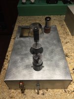
This is a photo of the chassis with three filler tubes in it to see how it will look. I took an aluminum Hammond chassis and put this pattern on it with a drill and wire brush instead of painting it. I've done it before, and it is a super low maintenance finish.
Attachments
> a good voltage and bias for the 6SL7
It is never wrong to copy from the Resistance Coupled Amplifier tables.
http://www.mif.pg.gda.pl/homepages/frank/sheets/093/6/6SL7GT.pdf page 2
We know your big bottle wants round-about 300V total, so start in the Ebb=300V column.
IRRC(?), the big bottle will stand a 500K grid resistor, here "Rs", so look for Rs=0.51Meg.
There are two choices: Rp=0.24Meg and Rp=0.51Meg. Both are quite high values for full 20KHz flatness, use the lower 0.24Meg. Or go up to Rp=0.1Meg (this made Fender famous) and assume you will do a hair better with the higher gridleak.
Gain 38 to 48. Max rms out at 5%THD is say 48 to 54.
Your likely big-bottle lines suggest 40V peak or 28V rms drive for full output. Not strained.
Note that the driver B+ must be cleaner than the big-jug B+, and the classic filter is R-C with some voltage drop. Taking 10%-20% drop in B+ leads to 10%-20% drop of maximum output (much less drop of gain). Hmmm, this does put you close to overload in the 'SL when the big jug is maxed-out. Then aim for small (5%) drop in R-C filter and use a large cap to filter despite the small R.
The 'SL current can be estimated as half of Ebb/Rp. Not exact but close enough to pick a B+ filter resistor and cap.
And of course you pick Rk from the table. If you are between two Ebb points, interpolate.
My gut says these values are "lean". In hi-fi with no production-cost hassle, I would pick Rk as next-smaller rather than next-larger. For "1300" I would grab 1,200.
Ah, your big B+ may be nearer 250V. So your 6SL7 can run-split-difference between 300V and 180V columns, with split-difference results.
So the 6SL7 will be near max when the big tube is completely flogged.
This is not a surprise. If a power tube has Mu well above 5, it can easily be driven by a triode eating the same general B+; if Mu is lower than 5 it may need a heroic driver to flog it well. OTOH low Mu is more conductance, current, low resistance, and vice versa for high Mu.
One tube will run about 5% 2nd harmonic near full output. Two tubes will do 5% each but in simple form the curves "cancel". 2nd harmonic may be much less than 5%. This result was known long ago, and probably still applies. The residual is a 3rd, less self-hiding, but at a lower level than either 2nd.
Thanks again PRR. I will give your post some consideration and then draw up a schematic that includes the power supply and post it before I jump in. So scary driving without a full map!
Most of the designs I have built required large resistance in series after the power tubes to bring down the B+ for the pre tubes. Having small resistors, or small chokes, instead seems like a more ideal situation. I'm going to try a couple of LC filters after the power tubes to see how that works out. I have a number of .5 to 2 Henry chokes lying around. Will less than 1 millivolt of ripple be okay for the 6SL7?
5998 amp preliminary schematic
Hi All.
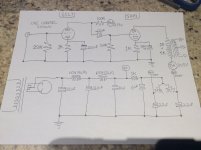
Here is my preliminary schematic for my new 5998 amp. I am using Hammond 125ESE OPTs because the transformers I was going to use were not gapped as I initially thought they were. This means that I will have a choice between 2.5 and 5K primaries and 4 and 8 Ohm secondaries. I figure I might as well put in a couple of switches to flip between 2.5K and 5K Ohm on the primary, and 4 and 8 Ohm on the secondary. According to PSUD I should end up with a B+ of 300 volts. I want to run the tube at 255 volts and 58 mA for a total dissipation of 14.8 watts. So 300 volts minus 40 volts for the cathode bias voltage and minus about 5 volts for the OPTs should leave me with 255 volts plate to cathode on the 5998. Please advise if the schematic makes sense as drawn, and of any revisions to it or suggestions that you may have. B+ ripple is about 3 millivolts, and the B+A ripple is .3 millivolts.
Hi All.
Here is my preliminary schematic for my new 5998 amp. I am using Hammond 125ESE OPTs because the transformers I was going to use were not gapped as I initially thought they were. This means that I will have a choice between 2.5 and 5K primaries and 4 and 8 Ohm secondaries. I figure I might as well put in a couple of switches to flip between 2.5K and 5K Ohm on the primary, and 4 and 8 Ohm on the secondary. According to PSUD I should end up with a B+ of 300 volts. I want to run the tube at 255 volts and 58 mA for a total dissipation of 14.8 watts. So 300 volts minus 40 volts for the cathode bias voltage and minus about 5 volts for the OPTs should leave me with 255 volts plate to cathode on the 5998. Please advise if the schematic makes sense as drawn, and of any revisions to it or suggestions that you may have. B+ ripple is about 3 millivolts, and the B+A ripple is .3 millivolts.
Attachments
I used a voltage tripler stacked on top of the +40v power rail on a mosfet amp to deliver 20 Ma of power at 135v to a 6922 pre stage using 2N5551 as regulator. ripple is less then 10 uV. No hum from power supply at all.
Tiny amount of hum is from the AC on the heater.
Tiny amount of hum is from the AC on the heater.
> if the schematic makes sense
Rectifier is drawn totally wrong.
Hammond 125xSE does not have primary taps, just a lot of secondaries. Personally I'd just bring them all out on a screw-strip and connect speakers to-taste.
Rectifier is drawn totally wrong.
Hammond 125xSE does not have primary taps, just a lot of secondaries. Personally I'd just bring them all out on a screw-strip and connect speakers to-taste.
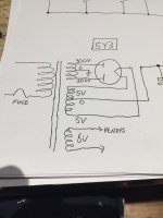
I glossed over the rectifier part. I didn't put in the rectifier secondaries etc. I'll do it properly in real life as per the attached drawing. I prefer switches to choose between 2.5K and 5K and 4 and 8 Ohm only. I'd prefer not to use a terminal strip, although that would give me complete flexibility. I'll sort that out. How about the rest of the circuit? Thanks!
Attachments
So I looked these tubes up as I've never heard of them before.
Similar to or the same as the 6AS7 or 6080 correct?
Do these sound good?
You don't see many amps using them in the output stage.
Ron
Similar to or the same as the 6AS7 or 6080 correct?
Do these sound good?
You don't see many amps using them in the output stage.
Ron
Amplification factor of 6AS7 is only 2, which means that the driver stage must have very different capacity.
The 5998 has an amplification factor of around 5. It seems that there is a sound quality scale that goes from 6080/6AS7 at the bottom, and then to the 5998, with the Western Electric 421A at the top. I have not heard an amp with any of these tubes in it yet, though I'm working on one right now. You tend to find 6AS7s in OTL amps, 5998s and 421As are generally in regular amps. The most famous example is probably the Fi 421A amp, which is a single ended stereo amp that uses one triode of the two triode 421A per channel. In that amp, the 421A is described as sounding somewhere between a 45 and a 300B. The 5998 is described as sounding good, but lacking some of the finesse of the 421A. Of course tubes always have more finesse and sound richer when they cost more😉. I believe that the 5998 and the 421A can be used interchangeably in amps made for either of them. I remember reading somewhere that they were both manufactured by Tung-Sol, and that the 421A had better matched triodes. The 421A costs $250-325 per tube, and the 5998 is usually $150-250. I am hopefull, of course, but I haven't heard either one. Yet.
It seems that there is a sound quality scale that goes from 6080/6AS7 at the bottom, and then to the 5998, with the Western Electric 421A at the top....
Or vice versa ? Depends on who, when, where and with which speakers has listened.
WE says the 5998 and 421a (ST envelope) are the same, and have a 13 W plate dissipation:
http://www.westernelectric.com/spec_sheets/421A.pdf
Tung-Sol has the 5998 listed in the ST envelope at 15W.
GE 5998A has a higher plate dissipation at 15W in the T-12 envelope.
So dissipation may depend on who the manufacturer was.
http://www.westernelectric.com/spec_sheets/421A.pdf
Tung-Sol has the 5998 listed in the ST envelope at 15W.
GE 5998A has a higher plate dissipation at 15W in the T-12 envelope.
So dissipation may depend on who the manufacturer was.
All mine are ST Tung Sol 5998s. They seem to all be the 15 watt types. Apparently the Fi 421A amp runs at a 15 watt dissipation and uses the 421A. Also, the 15 watt rating assumes air cooling. That said, the Fi 421A is not air cooled, and runs what is apparently a 13 watt tube at 15 watts.
In his earlier post, PRR said that he believes the ratings are very soft and that it can probably be run at higher dissipations safely, but with reduced tube life. He mentioned 17 watts for 5000 hours and 12 watts for 10000 hours. I suppose YMMV, but most of the designs I've seen for either tube run it at 15 watts per triode. I am shooting for 14.8 watts, but I may drop it a little to 14 or so.
> He mentioned 17 watts
You push the limit when compactness is VITAL. Aircraft etc.
There is no good reason for you to run 17W.
I suspect part of the 12W/13W/15W "differences" are about the intended uses of tubes sold through that channel. WE had billions of tubes all over the world working 24/7 with union-labor tube replacement workers. They would never be bold. Tung-Sol was proud of first their lamps then their tubes, and often did give high numbers which worked extremely well in applications short of telco-huts. I am mindful of the early Ampex quad video tape machines, which had a rack of Tung-Sol 6550s working at T-S's ratings and were workhorses in broadcast TV.
Is your life tougher than W-E's main applications? As tough as CBS TV's nightly schedule and production rooms? Odds are you can work to any of these ratings and never wear-out the tubes.
- Status
- Not open for further replies.
- Home
- Amplifiers
- Tubes / Valves
- 5998/421A build and schematic feedback wanted