Since I'm really happy with the sound of my gainclone, I'm going to build another one.
My first gainclone was a four-channel power amp version using the attached circuit, except for a fixed 100K resistor to ground at input.
For the new one, which will have a volume control, I wonder if can I use a 50K linear pot instead of a 100K pot? What are the drawbacks?
Thanks /Jan
My first gainclone was a four-channel power amp version using the attached circuit, except for a fixed 100K resistor to ground at input.
For the new one, which will have a volume control, I wonder if can I use a 50K linear pot instead of a 100K pot? What are the drawbacks?
Thanks /Jan
Attachments
try not to use a linear pot...unless you really have to or you are just experimenting...I guess 50K will work too...
What really is the difference with using linear tapers? For all of my amps, I always use a 25K 10% tolerance linear made by Allen Bradley (at least thats what the box says, I didn't buy them, I was given them).
Do the audio ones made a large difference?
Do the audio ones made a large difference?
li_gangyi said:try not to use a linear pot...unless you really have to or you are just experimenting...I guess 50K will work too...
OK, then I have a 100K log. pot I could use.
Does "linear taper" on the circuit not refer to a linear pot...?
Pots
I am again and again wondering that people use pots with high resistance in semiconductor circuity. It is relict of " tube age ", where gain stages had great output impedance, which must had only little " load ". Today, when typical output impedance of any semiconductor machine is 100 Ohm or lower, is it nonsens. In this case optimal resistance of pot should be approximately 1 kOhm, but it is very hard to made ( in logaritmical version ). So use 10 Kohm pot - you get lower noise and much more independet frequency charakteristic in every positions of pot.
I am again and again wondering that people use pots with high resistance in semiconductor circuity. It is relict of " tube age ", where gain stages had great output impedance, which must had only little " load ". Today, when typical output impedance of any semiconductor machine is 100 Ohm or lower, is it nonsens. In this case optimal resistance of pot should be approximately 1 kOhm, but it is very hard to made ( in logaritmical version ). So use 10 Kohm pot - you get lower noise and much more independet frequency charakteristic in every positions of pot.
Don’t wonder!
The reason of usage 100k is here more related to the goal of obtaining logarithmic curve with linear potentiometer since its wiper is always loaded with 10k resistor. This is the relict of the theory that the linear pot sounds better than logarithmic. (The theory has technical merits but I must say that my listening experience did not confirm this theory.) However, with logarithmic pot (and wiper loaded with 10k), the resulting curve might appear “overcompensated”.
But, more important: the circuit’s output impedance is not necessarily related to the circuit’s driving ability. Only a minor part of the transistor circuits around wouldn’t mind if you load them (even) with 10k.
Pedja
Upupa Epops said:I am again and again wondering that people use pots with high resistance in semiconductor circuity. It is relict of " tube age ", where gain stages had great output impedance, which must had only little " load ". Today, when typical output impedance of any semiconductor machine is 100 Ohm or lower, is it nonsens.
The reason of usage 100k is here more related to the goal of obtaining logarithmic curve with linear potentiometer since its wiper is always loaded with 10k resistor. This is the relict of the theory that the linear pot sounds better than logarithmic. (The theory has technical merits but I must say that my listening experience did not confirm this theory.) However, with logarithmic pot (and wiper loaded with 10k), the resulting curve might appear “overcompensated”.
But, more important: the circuit’s output impedance is not necessarily related to the circuit’s driving ability. Only a minor part of the transistor circuits around wouldn’t mind if you load them (even) with 10k.
With 220k in the feedback I'd rather use 50k than 100k pot.2Bak said:For the new one, which will have a volume control, I wonder if can I use a 50K linear pot instead of a 100K pot? What are the drawbacks?
Pedja
It is also my experience that 50k pot works better than 100k. And log taper works more realistic in IGC than a linear (by that I mean more uniform control range). It all depends on a split, but most common Japanese pots are usually 10/40 and not 10/90.
I'm using old production Nobel pots, 31 detented positions, mono. I match them before installing and it is not that hard to actually match them to 0.2dB or better accuracy. They also sound pretty good, very claean and not romantic.
I'm using old production Nobel pots, 31 detented positions, mono. I match them before installing and it is not that hard to actually match them to 0.2dB or better accuracy. They also sound pretty good, very claean and not romantic.
Pedja, I certainly know that this concrete circuit will have approximate logaritmic curve, but I say, that his impedance is too high, what is wrong in " noise look ". My note was general, not concrete to this circuit.
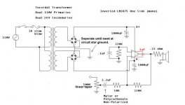
Had a look at the circuit above and have a few comments to make about it besides the question about the potentiometer
Firstly, why are two bridge rectifiers used, one connected as a Back to Back Bridge would do
Second, why only 1000 MFD used in the Power Supply Filtering, 4700 or 10000 MFD would be much better
Third, Why use a .22 Ohm Resistor in the Output, a small Inductor, damped by a suitable resistor would work better, and give you a better Damping Factor
Fourth, Why use the Inverting Input on the Amplifier Chip
This effectively places the Potentiometer, (as I understand) a Carbon one at that in the Feedback Loop
Carbon Resistors are no good in Feedback Loops, and will cause a certain amount of distortion
Ordinary Metal Film Resistors are Cheap, and much better
Suggest use the Non-Inverting Input, and use a 10 MFD Bipolar Electrolytic for the DC Coupling, and say a 47 or 100 MFD Bipolar Electrolytic for the Feedback Ground Isolation
Re Potentiometers
I suggest use a Professional 10 K Audio Taper ALPS Conductive Plastic Potentiometer, fairly expensive but very very good
Audio Taper is a slightly modified Log Taper
dude...you mudst be new to the GainClone scene...first 1000uF caps..they are there as they have been found to be the best sounding in this application...too much and the whoile thing becomes bassy...
Inverting input...he wants to build an inverting amp~!!
Carbon resistor...you are right...they do introduce distortion...but since he wants to build a inverting amp...I don't see how he can get rid of it unless he uses a metal film stepped att. network...
The dual bidge rectifiers are there as they have been found to give better performance compared to a single bridge rectifier...and it gives more flexibility...if he wants to use dual transformers...(I dunno why...maybe he doesn't have on of correct voltage)..but a single one COULD be used...tried it and it sound the same to me...(TO ME)...I realise that some of your statements make a lot of sense to a guy who doesn't mess with GCs too much...I'm not saying that I'm a GC pro...( go look for Peter Daniel)...groans...here starts the debate again...but I love debates...
poulkirk: These values have become a sort of religion, enough people knowing so little about the electronics behind the circuit using the same values that deviating from them is regarded as nearly blasphemic. The ones that do know something do not conduct scientific listening tests, and rely on their own hearing, tainted by the oddly illogical audiophile intuition(which usually includes many superstitions they have picked up along the way to becoming an audiophile, such as the "resonances" of certain case materials).
Even so, it's not that bad of a combination.
I'm making one for myself, inspired by all this hubbub, so what does that say about me? Then again, I AM using more caps, I AM using a regulated supply, I AM using some quite severe modifications, and I'm not under the impression that the gainclone is some highly unique circuit, the engineering of which requires some higher order of knowledge.
I'm not say that a regulated supply wun work...but you do need one that can supply a highcurrent at any given time...or else there might be "compression"...as to the cap values..yeah I also initially thought bigger means better...but seems not to be in the case of a GC...wonder why...perhaps we should ask National on this...
- Status
- Not open for further replies.
- Home
- Amplifiers
- Chip Amps
- 50K or 100K pot?