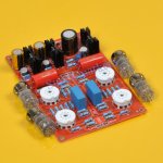
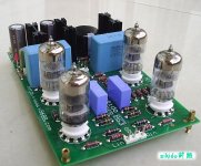
Hello guys, i bought a 4x6N3 preamp board. It is made by Yuan-jing, and the seller did not give any schematic, anybody can help me to understand what kind of preamp it is, or if somebody has a schematic ill be more than happy.
I have used it and is working, the board has 2x AC power inputs, one 12-15V AC and one 30 - 44V AC, From what i saw it is using 2x7812 for filaments, and one lm317 for anode curent limit.
I will attach the image of the board.
Hope i can find some help here.
4X 6N3 Tube Pre Amplifier Board | eBay
Thank you,
Attachments
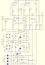
Difficult to say exactly whats going on--without schematic...
Possibly two SRPP stages capactively coupled, although would have thought 40V +B was a bit low for that........
Dunno--Email seller, ask for schematic!
Possibly two SRPP stages capactively coupled, although would have thought 40V +B was a bit low for that........
Dunno--Email seller, ask for schematic!
Its 40v - 44v AC input probably followed by a x4 multiplier. Which could give approx 220v DC.
What Voltage is the large black capacitor?
What Voltage is the large black capacitor?
Not enough caps for voltage multiplier.
The smaller cap has an 80V rating. Looks like FWB followed by the large cap. Probably 60V B+.
The smaller cap has an 80V rating. Looks like FWB followed by the large cap. Probably 60V B+.
Last edited:
Thank you all for fast answers, the big black cap is 220uf/63V.
I had measured and between anodes and Screen( which is Ground) i have 41V dc and 29V dc on each triode of the double triode pack.
Please forgive my mistake, on the AC Voltage, it is about AC12 or AC15V(20W) AC40 or 44V(10W), on the 15V can be up to max accepted by caps and LM7812 at the input, and on the 40 - 44V AC after rectifier, ful brdige diodes, came the lm317 which is used to limit the current not as a adjustable voltage regulator.
Last edited:
Attachments
Last edited:
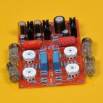
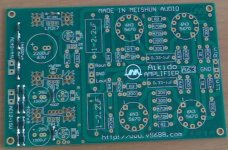
This is the one! Thank you Koonw !
This look like the one. Thank you for help and, may be will help others in the future.
This look like the one. Thank you for help and, may be will help others in the future.
Hello guys, i bought a 4x6N3 preamp board. It is made by Yuan-jing, and the seller did not give any schematic, anybody can help me to understand what kind of preamp it is, or if somebody has a schematic ill be more than happy.
I have used it and is working, the board has 2x AC power inputs, one 12-15V AC and one 30 - 44V AC, From what i saw it is using 2x7812 for filaments, and one lm317 for anode curent limit.
I will attach the image of the board.
Hope i can find some help here.
4X 6N3 Tube Pre Amplifier Board | eBay
Thank you,
😕
Well, how the Chinese part sounds?
I really expect less attention to the heater power line and more dedication to the plate power line, with voltage regulation for very low ripple. The designer could drive a combination of ((2 heaters in serial)//(2 heaters in serial)) which would give 12,6V plus 0,75A; a very practical figure for a L7812 with TO220 box and a cooler; 12V AC-0,7V *1,4142=15,9V. Lets hope for a 0,75A current the ripple value with a 2200uF is 1,21V, so the regulator should get at input around 14,7V. If its to close the operation limit, then get a 4700uF cap and about half the ripple is obtained and a practical 15V figure would left 3V*0,75A=2,25W drained as heat by that miserable heat sink.
Enough for now and tell us how it sounds and the voltage gain obtained.
Good luck with it.
😀
Hello Paluse,😕
Well, how the Chinese part sounds?
I really expect less attention to the heater power line and more dedication to the plate power line, with voltage regulation for very low ripple. The designer could drive a combination of ((2 heaters in serial)//(2 heaters in serial)) which would give 12,6V plus 0,75A; a very practical figure for a L7812 with TO220 box and a cooler; 12V AC-0,7V *1,4142=15,9V. Lets hope for a 0,75A current the ripple value with a 2200uF is 1,21V, so the regulator should get at input around 14,7V. If its to close the operation limit, then get a 4700uF cap and about half the ripple is obtained and a practical 15V figure would left 3V*0,75A=2,25W drained as heat by that miserable heat sink.
Enough for now and tell us how it sounds and the voltage gain obtained.
Good luck with it.
😀
I had tested the board, it sound quite good, with the chinese 6N3 tubes,
but i replaced them with NOS 6N3P-EV which are superuor tubes, and i have a fattest sound, with more low and mids.
I will change the caps on the heater side, with larger values, when i will find good quality caps, which i do not have on my component stock for the moment.
I plan to modify the HV part to have much higher voltage on the anode to get most of it out.
I had changed the rectifier diodes, because i found one acting like a wire, was on the heater side, and i replaced all.
Ill keep you posted guys when i will have all done and in case 🙂 with some pictures too.
Why do anyone purchase a kit when schematics is not included ??? Why even bother
when fully documented kits and readymade amps are available at closer range ?
In fact i warn against buying undocumented "strange kits" where the only reason to buy is "It's cheap". Yes it's cheap, but if not usable it is expensive ****.
when fully documented kits and readymade amps are available at closer range ?
In fact i warn against buying undocumented "strange kits" where the only reason to buy is "It's cheap". Yes it's cheap, but if not usable it is expensive ****.
Hey dude,Why do anyone purchase a kit when schematics is not included ??? Why even bother
when fully documented kits and readymade amps are available at closer range ?
In fact i warn against buying undocumented "strange kits" where the only reason to buy is "It's cheap". Yes it's cheap, but if not usable it is expensive ****.
First let me tell you that, it was not a kit, but a assembled board.
All the compunents already soldered, and i like to learn and experiment,
This is why you buy a low price board, i do love valves, but i do not like point to point,
and i dont want to make a pcb, i do not want to use the chemichals with 2 small kids around. What i don't understend is why you say what you say, in this manner? How do you expect to learn if not by asking people, and reading, and most important sharing the info?
I had searched for a schematic, and i got help from good people from here, to fond one. Thak you all guys for help, thank you diyaudiu.com for all the good job you do!
Dude, what was the point? How this kind of opinion, which i respect, cause is you opinion, will help me and other dudes ?
Love is the answer, to most of humanity problems!
Peace and love to you all.
Hello Paluse,
I had tested the board, it sound quite good, with the chinese 6N3 tubes,
but i replaced them with NOS 6N3P-EV which are superuor tubes, and i have a fattest sound, with more low and mids.
I will change the caps on the heater side, with larger values, when i will find good quality caps, which i do not have on my component stock for the moment.
I plan to modify the HV part to have much higher voltage on the anode to get most of it out.
I had changed the rectifier diodes, because i found one acting like a wire, was on the heater side, and i replaced all.
Ill keep you posted guys when i will have all done and in case 🙂 with some pictures too.
😛
Hi.
The higher voltage at the plate is a pleasant idea.
I have 2 6n3 buffer kits which have a Greinacher voltage "quadruplicator". The buffer's came as kits so I bought new parts and all the capacitors are audio grade and diodes are schottky type. The standard voltage obtain from the "quadruplicator" with 12V AC is 60V (+30V and -30V related to the ground voltage). I'm now testing it with a 15V AC transformer and the voltage is 80V and the tube works fine, but the heater DC regulator have a bigger heatsink to work in such input voltage (20V in to 6,3V out).
I also listen GE GL-5670, it have a more shut in midband and treble , a bit more bass and behave with more stability to higher input signals. Nevertheless the chinese 6n3 have a "tube sound" all the same...😀
So, get a higher voltage at the cathode power line is easy in your kit, but better quality caps and that voltage regulator (LM317) to ensure voltage stability and low ripple (more than -80db) is advise IMHO, to get very good sound, and I believe that's what is at the plate power line. Just get a top notch audio 10uF capacitor at the control pin, because is this guy who drives de LM317 to a -80db ripple. You don't have a current regulator anywhere.
Since your preamp is more complex than the buffer kit, a more carful planning is wise before turbo charge the plate.
Be kind and tell us how the project goes...
Good luck.
😉
Last edited:
😛
Ohhps, my mistake; it's not higher cathode voltage but higher plate voltage.
How it goes? Did you turbo charged the plate? With 65V AC you easily get 90V DC and for the LM317 works well a Voltage drop of 5V is enough, which give's you 85V stabilized . Remember the "Heater Cathode Voltage" is 90V Max for GE GL-5670 and 100V for 6N3. It's said if this value is surpassed it reduces heavily the tube life (MTBF).
I've my doubts if this 4X6N3 board it's really good "sounding".
When you get more news about sound quality and voltage gain, just let us know.
Bye
😉
😕
Hi quassar.
I've received my board. Looks like yours, but the electrolytic caps and some resistors should be replaced.
The mystery for now is the plate voltage. In my board the plate voltage seems target for 48,5 V. The capacitor at the LM317 output is rated for 50V, but I'll check the tube graphs in the datasheet.
A previous check should be done to evaluate the possibility of a higher plate voltage and it's consequences in this circuit.
Still waiting for your news.
😀
You can change the caps too
Hey, sorry for late reply,you can change the electrolytic capacitor with higher voltage rating, for just in case.
I decided to build an EL34 SE, and did not have enough time to finsh the enclosure for the aikido clone with 6N3P's. Ill keep you in the loop 🙂
😕
Hi quassar.
I've received my board. Looks like yours, but the electrolytic caps and some resistors should be replaced.
The mystery for now is the plate voltage. In my board the plate voltage seems target for 48,5 V. The capacitor at the LM317 output is rated for 50V, but I'll check the tube graphs in the datasheet.
A previous check should be done to evaluate the possibility of a higher plate voltage and it's consequences in this circuit.
Still waiting for your news.
😀
Hey, sorry for late reply,you can change the electrolytic capacitor with higher voltage rating, for just in case.
I decided to build an EL34 SE, and did not have enough time to finsh the enclosure for the aikido clone with 6N3P's. Ill keep you in the loop 🙂
Hey, sorry for late reply,you can change the electrolytic capacitor with higher voltage rating, for just in case.
I decided to build an EL34 SE, and did not have enough time to finsh the enclosure for the aikido clone with 6N3P's. Ill keep you in the loop 🙂
😛
Hi.
The new parts are already with me, but I've got to finish an older project first...
The plan includes a 71V/8200uF Nichicon LKS after the rectifiers plus a 330uF /63V Nichicon Fine Gold after the LM317 and an Elna Silmic II 10uF/100V at the control pin of the LM317.
New caps for the heaters power line; Nichicon KW after Graetz rectifiers and Fine Gold after 7812 regulators. Also the two 1uF MKP capacitors at the noise rejection block are to be replaced by 2 WIMA MKP 1uF 250V.
An externally hosted image should be here but it was not working when we last tested it.
Nichicon LKS "Beast".
An externally hosted image should be here but it was not working when we last tested it.
A little mode at the value of resistor after the voltage pot can get the voltage at 62V for the plate. All 470K resistors will be replaced by 1% metal film 1/2W, as the R5 (82K) at the noise rejection line. All rectifiers are 2A/600V ultra fast type.
Four General Electric GL-5670 are ready to operate in the PCB, but first I have to measure the amp gain, check distortion values and overload margins at the input.
😉
😀
Hi good people.
Now I have the "New blocks for the kid" installed...

😉
I changed the resistor at the control line to accommodate a voltage window from 65V to 48V with the 2K pot. A more than 63V its not recommended because the output filter cap for the plate voltage is rated to 63V DC. Nevertheless I believe that a stress of 2 Volts above the recommended voltage is acceptable for the cap; an excess of 3,2% above the rated value.
All the Graetz bridges rectifiers are "Ultrafast type" with 2A and 600V reverse voltage
Only the original 5% 470kOhms resistors remain to be replaced by MF, 1%, 0,5W type. This values is used for the input/output load and the voltage divider for the plates of the drive and constant current source triodes.
The power transformer is ready to be picked up at the workshop.
I have to wait a bit more for testing.
Cheers
😛
Hi good people.
Now I have the "New blocks for the kid" installed...
An externally hosted image should be here but it was not working when we last tested it.
An externally hosted image should be here but it was not working when we last tested it.
😉
An externally hosted image should be here but it was not working when we last tested it.
I changed the resistor at the control line to accommodate a voltage window from 65V to 48V with the 2K pot. A more than 63V its not recommended because the output filter cap for the plate voltage is rated to 63V DC. Nevertheless I believe that a stress of 2 Volts above the recommended voltage is acceptable for the cap; an excess of 3,2% above the rated value.
All the Graetz bridges rectifiers are "Ultrafast type" with 2A and 600V reverse voltage
Only the original 5% 470kOhms resistors remain to be replaced by MF, 1%, 0,5W type. This values is used for the input/output load and the voltage divider for the plates of the drive and constant current source triodes.
The power transformer is ready to be picked up at the workshop.
I have to wait a bit more for testing.
Cheers
😛
🙂
I've run this board for some time, but the channels have an uneven performance. I believe the 6n3 are the main responsible, but I detect more misbehaviour. For instance the floating voltage between the CCS triode and the input triode at the voltage section is different from one channel to another and with the tubes switch. The resistors values are very tight, so I have to discover what's happening here. I hope the 6n3 tubes aren't sensitive to the heater current direction flow...
The gain is around 20db (10X). I also have to try a solution to reduce the voltage gain to 7db without get more distortion at the voltage gain stage.
The Plate voltage can be adjust from 47V to 63V.
😀
Bye
An externally hosted image should be here but it was not working when we last tested it.
Last edited:
🙂
I've run this board for some time, but the channels have an uneven performance. I believe the 6n3 are the main responsible, but I detect more misbehaviour. For instance the floating voltage between the CCS triode and the input triode at the voltage section is different from one channel to another and with the tubes switch. The resistors values are very tight, so I have to discover what's happening here. I hope the 6n3 tubes aren't sensitive to the heater current direction flow...
The gain is around 20db (10X). I also have to try a solution to reduce the voltage gain to 7db without get more distortion at the voltage gain stage.
The Plate voltage can be adjust from 47V to 63V.
😀
Bye

Please read http://www.diyaudio.com/forums/tube...be-preamp-dc-dc-converter-13.html#post4564007
I don't want to repeat, sorry about the inconvenience.
- Status
- Not open for further replies.
- Home
- Amplifiers
- Tubes / Valves
- 4x6N3 preamp board from ebay