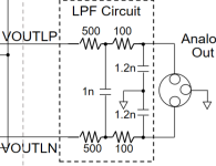
I'm designing a DAC + HPA based on TPA6120 with the XLR output level of 4Vrms and PSU voltages of +/-15V. I'd like to use TPA6120 in a differential configuration (see attached TPA6120 circuit) taking an input differential signal directly from the XLR output after a XLR LPF (see attached XLR circuit).
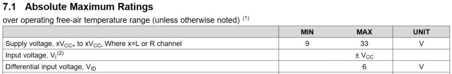
I noticed that the absolute maximum differential input voltage rating for TPA6120 is 6V (see attached TPA6120 Absolute Maximum Ratings table). I assume it's 6Vpp, not 6Vrms.
Questions:
1. When a DAC spec for XLR output level claims 4Vrms, does it mean that each individual V+ and V- XLR lines should have 2Vrms level w.r.t. ground?
Then, 2Vrms * 2.82 = 5.64Vpp level on each of V+ and V- XLR lines w.r.t. ground?
2. If there would be 5.64Vpp level w.r.t. ground on each of V+ and V- XLR lines, does it mean TPA6120's differential inputs could potentially see a max voltage of 5.64Vpp * 2 = 11.28Vpp?
3. Since the 11.28Vpp differential inputs voltage is higher than the absolute maximum differential input voltage rating for TPA6120 of 6Vpp, both the XLR lines should be attenuated down about 2x times. It will make them to be around 2.82Vpp w.r.t. ground each. If so, what could be a good schematic for the attenuator?
I might be wrong on some or all of those assumptions above 🙂 Any input\ideas are highly appreciated.
Attachments

Last edited:
But the differential voltage is tiny/zero as the TDA6120 acts to ensure that - assuming its powered up of course.
With two antiphase signals of 5.64V p2p, they both vary from -2.82V <-> +2.82V w.r.t. ground, since 2.82 - -2.82 = 5.64. But again the amp chimp doesn't see the differential input voltage, its sees its DC offset voltage modulated by a tiny fraction of the incoming signal.
With two antiphase signals of 5.64V p2p, they both vary from -2.82V <-> +2.82V w.r.t. ground, since 2.82 - -2.82 = 5.64. But again the amp chimp doesn't see the differential input voltage, its sees its DC offset voltage modulated by a tiny fraction of the incoming signal.

I noticed that the absolute maximum differential input voltage rating for TPA6120 is 6V (see attached TPA6120 Absolute Maximum Ratings table). I assume it's 6Vpp, not 6Vrms.
It's neither, it's just 6 V maximum differential voltage. That is, at no time should the voltage between the pins exceed 6 V in either direction, so the maximum allowable peak-peak voltage is 6 V - (-6 V) = 12 V if there is no DC component.
Anyway, it's all irrelevant because of what Mark wrote.
But the differential voltage is tiny/zero as the TDA6120 acts to ensure that - assuming its powered up of course.
Thank you for clarifying things! Is it because TPA6120 has a closed feedback loop, so it maintains the differential input voltage at zero volts, correct?
With two antiphase signals of 5.64V p2p, they both vary from -2.82V <-> +2.82V w.r.t. ground, since 2.82 - -2.82 = 5.64. But again the amp chimp doesn't see the differential input voltage, its sees its DC offset voltage modulated by a tiny fraction of the incoming signal.
After your explanation. it makes more sense to me, thank you! I've missed the point that both of those voltages are +/-2.82V w.r.t. ground, so the max differential amplitude between them could therefore be 5.84V only.
Also with all of this in mind, could you tell what are real-world implications of that 6V max differential input voltage? Does it come to play when powering up and down only?
Last edited:
Thank you! After Mark's answer, I get that it's irrelevant in terms of the 4Vrms input signal, but I'm not sure I follow the 6 V - (-6 V) = 12 V math here.That is, at no time should the voltage between the pins exceed 6 V in either direction, so the maximum allowable peak-peak voltage is 6 V - (-6 V) = 12 V if there is no DC component.
Anyway, it's all irrelevant because of what Mark wrote.
If 6V is the max possible voltage difference between + and - input pins in either direction, then I understand it as:
1. the + pin can't see more than 6V w.r.t. the - pin.
2. the - pin can't see more than -6V w.r.t. the + pin.
I don't see how it could go up to 12V here. Am I missing something?
Actually after my initial answer to you, I've realized I'm still confused. If both of those voltages are +/-2.82V w.r.t. ground and the max differential amplitude between them could be 5.84V only (which is 2Vrms), why does one claim it to be 4Vrms XLR output signal in the specs, then?With two antiphase signals of 5.64V p2p, they both vary from -2.82V <-> +2.82V w.r.t. ground, since 2.82 - -2.82 = 5.64.
Last edited:
Thank you! After Mark's answer, I get that it's irrelevant in terms of the 4Vrms input signal, but I'm not sure I follow the 6 V - (-6 V) = 12 V math here.
If 6V is the max possible voltage difference between + and - input pins in either direction, then I understand it as:
1. the + pin can't see more than 6V w.r.t. the - pin.
2. the - pin can't see more than -6V w.r.t. the + pin.
I don't see how it could go up to 12V here. Am I missing something?
Suppose that at time t1 the positive input is 6 V higher than the negative input. By definition, the differential voltage is then +6 V.
Suppose that at time t2 the positive input is 6 V lower than the negative input. By definition, the differential voltage is then -6 V.
Now suppose the voltage moves up and down between these values. The positive peak differential voltage is then +6 V and the negative peak differential voltage is -6 V. The peak-to-peak voltage is by definition the difference between them, which is +6 V - (-6 V) = 12 V.
MarcelvdG, makes perfect sense to me now! Thanks a lot!
It seems the last and kind of important question left with this design for me is in this post:
i.e. why +/-2.82Vpp w.r.t. ground voltage on both of + and - lines of XLR output is claimed as 4Vrms in specs? Or do I misunderstand something here as well? I'd appreciate some guidance on this one!
It seems the last and kind of important question left with this design for me is in this post:
Actually after my initial answer to you, I've realized I'm still confused. If both of those voltages are +/-2.82V w.r.t. ground and the max differential amplitude between them could be 5.84V only (which is 2Vrms), why does one claim it to be 4Vrms XLR output signal in the specs, then?With two antiphase signals of 5.64V p2p, they both vary from -2.82V <-> +2.82V w.r.t. ground, since 2.82 - -2.82 = 5.64.
i.e. why +/-2.82Vpp w.r.t. ground voltage on both of + and - lines of XLR output is claimed as 4Vrms in specs? Or do I misunderstand something here as well? I'd appreciate some guidance on this one!
I think you are confusing peak and peak-to-peak.
4 V RMS differential signal means that the difference between the two voltages is 4 V RMS. If everything is symmetrical, you have 2 V RMS at one output and 2 V RMS in the opposite phase at the other output.
For a sine wave, 2 V RMS corresponds to 2√2 V peak. Hence, each output varies between -2√2 V and +2√2 V momentary voltage.
The peak-to-peak voltage at each output with respect to ground is then +2√2 V - (-2√2 V) = 4√2 V. The peak-to-peak differential voltage is twice as high.
Ok, I think I got my mistake. I was missing the fact that momentary voltage between peaks on + and - lines swings between +2√2 V - (-2√2 V) = +4√2 V and -2√2 V + (-2√2 V) = -4√2 V since they're in anti-phase. This, in turn, gives +4√2 V - (-4√2 V) = 8√2 Vpp which equals to 4Vrms.
Now, it seems right to me that if I'd make both the + and - lines to output 4√2 Vpp each this would correspond to the 4Vrms XLR spec. Previously, I thought that for the 4Vrms XLR spec, I'd need both the lines to output 8√2 Vpp each.
So basically, signal level on all lines of 2Vrms RCA and + and - of 4Vrms XLR have exactly the same voltage w.r.t. ground while, at the first glance, the lines of the XLR output seemingly should have double the voltage of the RCA output line, but it's not actually true.
This also explains why a RCA LPF generally has a gain of 0.5 if its opamp inputs are connected to an XLR output if a device has 2Vrms RCA and 4Vrms XLR outputs.
Hopefully, this makes sense 🙂
Last edited:
- Home
- Amplifiers
- Headphone Systems
- 4VRMS XLR level and TPA6120 max differential input voltage rating