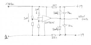
I would like to know if i've missed something with this idea before I blow up some expensive hardware.Is converting a standard first watt +/- 23 volt supply to +46 volts simply a matter of moving the center point "ground" to the negative rail point? I mention "ground" because there is a CL60 between the common and actual ground as per usual practice.The supply has chokes instead of the low ohm resistors in the CRC ie: it's a CLC.Currently the only common point is between the last capacitors in the supply,there is no connection between the 2 transformer secondaries.
do not do that, unless you know what you're doing
you need mid point, proper or artificially made, to power existing circuit , made for dual rails
other way is to change amp circuit, to accommodate single rail supply ....... and that demands both input and output caps
there are few threads how ppl did artificial GND, but I can't remember proper key words for search
do not do that, unless you know what you're doing
you need mid point, proper or artificially made, to power existing circuit , made for dual rails
other way is to change amp circuit, to accommodate single rail supply ....... and that demands both input and output caps
there are few threads how ppl did artificial GND, but I can't remember proper key words for search
I'm not sure what you mean,by "mid point" do you mean the common between the upper + half and the lower - half? If so I would not remove that connection,just move the ground from there to the negative rail point.Thank you for your help.
If you are uncertain about the idea of creating a mid point in your amplifier circuit, then it would be best to not try the conversion.
Perhaps it may be simpler to show the precise schematic (along with your proposed modifications) for the PSU you're considering along with the schematic for the amp circuit.
You want to have just a unipolar 46V power supply (only "+" and GND), right ?
Not bipolar and no GND in the middle ...
The only potential issue I see with your solution from post #7 could be the choke in the "ground" / 0V line ... don't know if that would create problems.
Regards, Claas
Not bipolar and no GND in the middle ...
The only potential issue I see with your solution from post #7 could be the choke in the "ground" / 0V line ... don't know if that would create problems.
Regards, Claas
This is what i am talking about.So this is a no no.If so i'll think about a switching supply.
This would be fine. The two floating supplies are joined only at their outputs, plus to minus,
with no other connections. It does not matter in which branch the inductor is located.
Last edited:
Oreo - what amplifier are you building?
yes, that information is crucial
besides that, what we are talking here - it's called simply as "stacked supplies", nothing new and nothing wrong, under condition that each one is having both outputs floating - GND and Safety GND- free
I was first thinking that question is related to existing bipolar supply in function of amplifier using the same
Oreo - what amplifier are you building?
I'm building a F8'ish.I have a F7'ish and would like to use the existing chassis and ps with minimal mods so if it doesn't work out I can go back.
This would be fine. The two floating supplies are joined only at their outputs, plus to minus,
with no other connections. It does not matter in which branch the inductor is located.
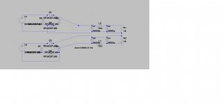
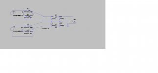
BTW,i made a mistake with the Spice pic I posted.The 2 ,16 ohm resistors across each half wouldn't be there but the connection between top and bottom half would.I then redid my spice sim and noticed with a resistor of around 16 ohms across the + and ground points simulating a roughly 2.6 amp load the voltage drops to about 43 volts.
Attachments
just for clarity sake
if you GND lowest tap, you then have +21.5 and +43V taps above
if you GND mid tap, you have +21.5V above and -21.5V down
if you GND top tap, you have -21.5 and -43V down
as always, GND is state of mind

if you GND lowest tap, you then have +21.5 and +43V taps above
if you GND mid tap, you have +21.5V above and -21.5V down
if you GND top tap, you have -21.5 and -43V down
as always, GND is state of mind
I then redid my spice sim and noticed with a resistor of around 16 ohms across the + and ground points simulating a roughly 2.6 amp load the voltage drops to about 43 volts.
It's normal for an unregulated supply to drop 5% to 10% under full load,
from the open circuit voltage, unless it's extremely over-designed.
The 23V are typically the under-load voltage of the usual FirstWatt PSU. Probably your unloaded voltage will be higher with 18V AC secondaries.
- Home
- Amplifiers
- Pass Labs
- 46 Volt Power Supply