Could someone explain how this circuit works to boost 40hz. Its a variable boost and I don't understand how the second op-amp provides gain. I've circled the portion in red. Ok, my brain hurts! Does it pickup its source from ground and pass through 56k into non-inverting then out of the op-amp through 2.7k and 2.2uf then into the variable resistor?
Attachments
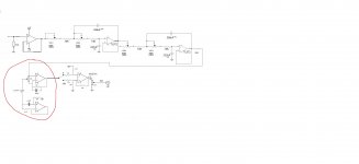
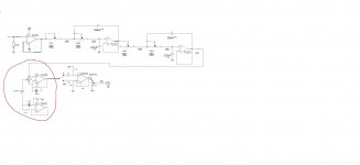
the op-amp in red is an inductance emulator of 6 something Henries with about 53K in parallel and 2.7K in series with the parallel RL. along with the 20K pot acts as a variable NOTCH at about 40Hz. a really awkward design!
You can build a common EQ boost/cut circuit and only use the boost (one example).
This circuit uses three filters to increase/decrease the feedback for a range of frequencies. The more feedback, the more cut. Less feedback results in greater output at that band.
The old Rockford circuit is relatively simple but requires a reverse log pot to make it easily adjustable.
This circuit uses three filters to increase/decrease the feedback for a range of frequencies. The more feedback, the more cut. Less feedback results in greater output at that band.
The old Rockford circuit is relatively simple but requires a reverse log pot to make it easily adjustable.
Thanks... I should have read Elliott Sound Products as there is a nice explanation on this... Parametric and Sub-Woofer Equaliser
The particular crossover I drew this from I've had laying around for about 15 years. I benched it with a sig gen and scope. With 1 volt in @ 40hz and no boost it puts out about 1.2 volts. (This is just one of the channels.) When the boost is turned up to full the output goes to 7 volts with a decent looking sine-wave. I thought, that's a heck of a boost!
Scott
Last edited:
- Status
- Not open for further replies.