Hi everyone,
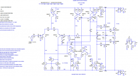
I've designed this amplifier based on NE5532 opamp, that has 3 voltage gain stages, I wanted to test it because it has an enormous open loop gain and it's an interesting design, the problem is the frequency compensation, it seems almost impossible to add a dominant pole capacitor, I've also tried to use MIC, and the ac simulation has shown good results, but when I try to do a transient analysis the simulation runs slowly and oscillations appear. Can someone help me here?
Best regards,
Daniel
Attachments
Op amp circuits don't typically translate into good discrete circuits. Op amps can provide some performance parameters that are virtually impossible to translate into discrete designs, because of their thermal tracking and very close tolerances in the individual device even though tolerance from device to device can be as high as 30%. Op amps also behave differently at high frequencies because of their physical size.
I can understand why you would emulate the 5532; it provides very good performance in an inexpensive and simple to use package. These virtues will not translate to a discrete circuit unfortunately.
I think it's the input stage that is its secret; the 5532 is far from an ideal op amp specwise but it works very well in audio circuits. Doug Self's "Blameless" amplifier has sorted all this out for discrete designs. Take a look at it if you haven't already; his input stage is highly optimized and maybe you could emulate that for your own design.
Poles "stack up" and cause problems with high open loop gain circuits if not properly sorted. Rule of thumb is to have poles separated by a decade; but this is not always practical. The fewer the poles the easier it is to sort out; one way around this dilemma is to use a two stage circuit. Dominant pole should be in the first (ideally) or second voltage gain stage. Output stage should be as fast as possible.
I believe the 5532/4 used very complicated nested/feedforward compensation even though exposing a nominal dominant pole external adjustment - I have only seen a good explanation with detailed circuit in one graduate level analog design textbook - I'd have to do some digging for the reference
found it:
found it:
the only place I have seen the 5534 internal compensation discussed in any depth is Huijsing, "Operational Amplifiers, Theory & Design" 2001
Last edited:
I believe the 5532/4 used very complicated nested/feedforward compensation even though exposing a nominal dominant pole external adjustment - I have only seen a good explanation with detailed circuit in one graduate level analog design textbook - I'd have to do some digging for the reference
found it:
The 5534 has internal compensation capacitors. The schematic is in this pdf file. http://www.ti.com.cn/general/cn/docs/lit/getliterature.tsp?genericPartNumber=ne5534&fileType=pdf
This device (5532 similar) is certainly not intended for a high precision DC circuit; its input impedance is 100K nominal (30K min). Both 5532 and 5534 are optimized for medium bandwidth AC signals. I've heard that taking the output from pin 5 (external compensation pin) of a 5534 (where the AC signal is still class A) and feeding it to an external class A buffer works great for audio, but I haven't tried it yet.
In my opinion, there are several reasons why op amp circuits do not translate into practical discrete circuits. That doesn't mean that we can't glean a few ideas from them. 😉
check your circuit carefully. a regular diff amp inverts between the input and VAS, but your circuit inverts twice,,,, try swapping the feedback connection and the input connection on the first diff amp... you might find the simulator will like it a lot better..... i've made a similar error a couple of times with LTSpice, so now if the sim crawls and the circuit oscillates, i look to see if i've got the correct number of inversions.
- Status
- Not open for further replies.