See trioda.com/index.php/pl/narzedzia/2131-program-wspomagajacy-dobor-punktu-pracy-triody for a full set of equations
kind regards
Marek
kind regards
Marek
RDH4 pages 563 and 564 give calculation methods for 2nd, 3rd and 4th harmonics. Section B page 564 (Esply) looks to be most practical.
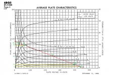
If you use test points in the plate knee region, you are going to get awful results. (point 1a on your graph is too far into the knee)
If you use test points in the plate knee region, you are going to get awful results. (point 1a on your graph is too far into the knee)
RDH4 pages 563 and 564 give calculation methods for 2nd, 3rd and 4th harmonics. Section B page 564 (Esply) looks to be most practical.
If you use test points in the plate knee region, you are going to get awful results. (point 1a on your graph is too far into the knee)
See trioda.com/index.php/pl/narzedzia/2131-program-wspomagajacy-dobor-punktu-pracy-triody for a full set of equations
kind regards
Marek
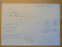
I'm not sure this will answer your question, but it's probably better than no answers. See attachment.
so, the right formula is this:
50* [Ia - (2 * Ib) + (2 * Id) - Ie / (Ia + Ib - Id - Ie)]
this would give a result of: 17.5%
so the tube datasheets are very optimistic talking about a 3rd HD of 8% about a Vp=250 Vg2= 250v Ra=4k5
Or your calculations are wrong ... anyway I don't think this theoretical approach will give accurate results for distortions .
that formula is also confirmed by RDH4 pages 563...
it also seems very strange to me that there is such a marked difference
it also seems very strange to me that there is such a marked difference
The tube's screen grid would burn up where the left most data points are located. Distortion would be expected to be very high there. Move the data points out into the flat/linear portion of the curves to get realistic numbers. (maybe you are using DC V instead of AC signal V to set points?)
Last edited:
The tube's screen grid would burn up where the left most data points are located. Distortion would be expected to be very high there. Move the data points out into the flat/linear portion of the curves to get realistic numbers. (maybe you are using DC V instead of AC signal V to set points?)
That's one of the load lines recommended in the datasheets ... to change those points I would also have to change the load line
Same load line. Just move the left most points to higher voltages, out of the knees. If the V positions are some percent of voltage swing, use the % AC voltage swing over the linear region selected. (not % absolute DC V)
Last edited:
Same load line. Just move the left most points to higher voltages, out of the knees. If the V positions are some percent of voltage swing, use the % AC voltage swing over the linear region selected. (not % absolute DC V)
I'm sorry, I didn't understand ... to move Ia and Ib without changing the line I have to go, for example, from Vg = -8 to Vg = -9 ... in this way the range between Ia and Ib is widened, but it is compress the one between Id and Ie
The Tungsol vers of the data sheet shews the information on 3H you are looking for.🙂
I was just commenting on that ... TS datasheet gives some results and instead that formula gives different ones.... in that configuration with about 5 w of power, in the distortion graph on the datasheet it should have 2nd = 6% and 3rd = less than 5%
Last edited:
- Home
- Amplifiers
- Tubes / Valves
- 3rd HD formula